This thread has been locked.

If you have a related question, please click the "Ask a related question" button in the top right corner. The newly created question will be automatically linked to this question.

TDES954&TDES953 I2C communication issue

Other Parts Discussed in Thread: TDES954, TSER953

Hello everyone, 

I encountered some werid problems when debugging the tdes954 and tdes953 chip, which troubled us for a long time.

It is aboout i2c bus issue, the following is the details:

I connect a  ov5647 sensor to the tdes serial device, and connect it to the RPI platform. After init the device, I can detect 

the device address as normal  shown as the follow image: so I think the tdes device is normal.

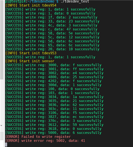
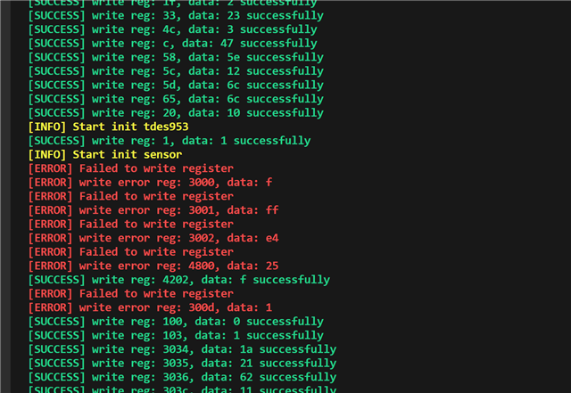
And then, when I try to init the camera, the issue occurred, I wirte a test script to write the sensor register, it will return a error.
   

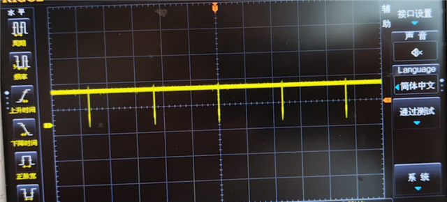
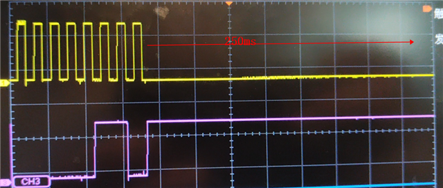
I grab the i2c write timing. and see after the eighth clock the chip will stretch the sck to low level and keep

 pulling it low until the host time out and exit.  the low time up to 250 ms, which is abnormal. 
   

I try to add delay between init tdes954 and tdes953 chip but the same result.
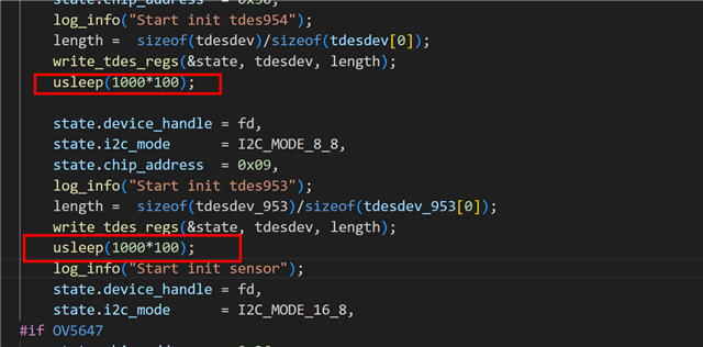
This is the source code 

tdesdev.tar.gz

Another issue: 

After init the tdes954 deivce and camera, I need to reinit the tdes device to get image. I don't know why.

As I understand, after init the tdes deivce, I just need to configure the camera and get image instead of init the 

tdes devuce after each the camera stream on.

  • Hello, 

    1. What is the maximum time for delay that has been tried for I2C communication following the soft reset of the serializer? 
      1. When using PDB (which matches a hard reset) there should be a minimum delay of 2ms. Following the soft reset of the 953, there will be a reinitialization of lock between the TDES954 and TSER953. 
    2. Would you be able to share a schematic of the TDES954 and TSER953? 
    3. Is the I2C issue seen consistently following the reset of the serializer? 

    Best,

    Zoe

  • Hello,

    Thanks for your quick respond.

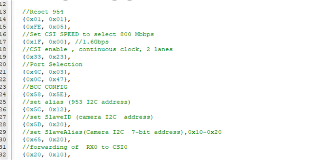
    1. The following code is my detail init parameters

    struct sensor_regs tdes954_rx0[] = {
    	
    	//Reset 954
    	{0x01, 0x01},
    	//Reset 954
    	{0x01, 0x00},
    	//Set CSI SPEED to select 800 Mbbps
    	{0x1F, 0x00}, //800Mbps  
    	//CSI enable , continuous clock, 2 lanes	
    	{0x33, 0x23},
    	//Port Selection
    	{0x4C, 0x03},
    	{0x0C, 0x47},
    	//BCC CONFIG
    	{0x58, 0x5E},
    	//set alias (953 I2C address)
    	{0x5C, 0x12},
    	//set SlaveID (camera I2C  address)
    	{0x5D, 0x20},
    	//set SlaveAlias(Camera I2C  7-bit address),0x10-0x20
    	{0x65, 0x20},
    	//forwarding of  RX0 to CSI0
    	{0x20, 0x10},
    };
    
    
    struct sensor_regs tdes953_tx0[] = {
    	//953 continuous clock, 2 lanes
    	 {0x02, 0x52},
    };


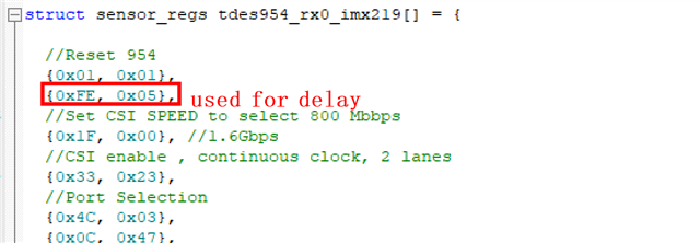
    Where should I add the delay? Between {0x01, 0x01} and{0x01, 0x00}?  Is it tdes954‘s software reset? For the tdes953, I just write  {0x02, 0x52} without any other operation.

    The totally operation is after wirte the sensor_regs tdes954_rx0 parameters,  just write  {0x02, 0x52}. Can you tell me how to add software reset of tdes953 chip?

    2. I thought it would be better to send the schematic via email.

    3. Each time the  camera streams on, I need to init the tdesdev, and the i2c error is very random.

  • Hello, 

    In the TDES initialization sequence, 0x01 does not need to be written to 0x00 as the reset bits are self clearing. This register write would not impact the operation, this is just a recommendation for optimization. The delay would be added following the register write of 0x01=0x01.

    Additionally, in the provided photo below, it appears like the start init for the TSER953 is writing register 0x01 to 0x01. Is this corresponding to 0x02 to 0x52? 


    I will wait to see the schematic via email. 

    Best,

    Zoe

  • Hello Zoe Bison,

    Thank you so much. You are so attentive. This message is indeed a mistake I made when testing the demo. It has been corrected.

    What's more, about the reset, you mean after I write the tdes954 software reset(0x01, 0x01), just add more 2 ms delay instead of writting (0x01, 0x00), right?

  • Hello, 

    What's more, about the reset, you mean after I write the tdes954 software reset(0x01, 0x01), just add more 2 ms delay instead of writting (0x01, 0x00), right?

    Yes, this delay is recommended for resets on the TDES954 and TSER953. The delay following the write of 0x01=0x01 will ensure the device is ready to receive the next I2C transaction. One additional comment is we typically recommend using a time delay in the format of a software wait, instead of issuing a transaction to 0xFE, as the I2C bus will not have the extra transactions. 

    Via email, it appears the issue was resolved following these suggestions but, please let me know if any additional support is desired.

    Best,

    Zoe

  • Hello Zoe,

    Thanks your your support. About the 0xFE, this is my protocol command and my API will parse it and add delay time. 

    Another issue. I find  on the raspberrypi platform, after the camera streaming on,  I need to reinit the tdesdev again to ensure it can receive image timming normal. You can see the detail steps here:

    step1: init tdes954 and tdes 953 

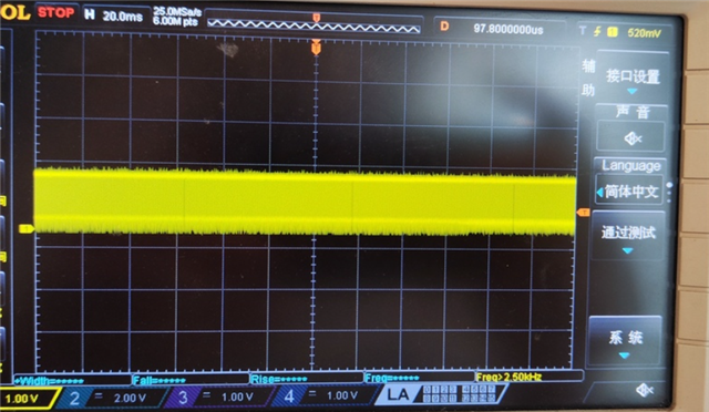
    step2: init camera configuration and stream on the camera, the I can grabe the mipi timing from the sensor. Shown as the below image:

       Grabe timing from camera 

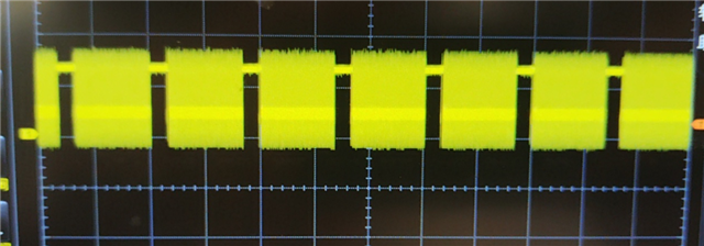
    But the raspberrypi can't get image normally due to the defective image timing from the tdes954 device. Shown as below

    Grabe timing from tdes954 

    You can see the timing is different from the camera port. But when I reinit the tdes954 device, it will come back to normal

    After add tdes954 init again it

    So, at present, if I want to use  it normal I shoud do the following work: init tdesdev -> init camera -> init  tdesdev again. I am not sure if it is  normal. 

    Do you have any suggestions?

  • Hello,

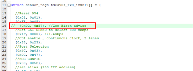
    Thank you for the clarification on the register write. Does inittdesdev include the register write of 0x02=0x57? 

    Additionally, referring to the initialization sequence, would you be able to confirm the register writes are as intended?

    //forwarding of RX0 to CSI0
    {0x20, 0x10},

    0x20=0x10 disables forwarding for Port 0 and enables Port 1

    0x20=0x20 enables forwarding of RX port 0 and disables forwarding of RX port 1

    //Set CSI SPEED to select 800 Mbbps
    {0x1F, 0x00}, //800Mbps

    0x1F = 0x02 for 800 Mbps serial rate 0x1F = 0x00 is for 1.6Gbps

    Best,

    Zoe

  • Hello, 

    Sorry for my late reply due to my other arrangerments those days.

    Yes, I have notice the 0x20 and  0x1F register, and it is normal. 

    About the 0x02 register, when I try to add {0x02, 0x57}, I can't get any image data from camera.  I have to delete it and it  can get image but need to reinit the tdesdev after the camera streams on.

  • Hello,

    Due to US holiday, the team will be out until Monday. We will resume activity next week. Thank you for your patience

    Best Regards,

    Casey 

  • Hello, 

    Apologies for the confusion, the register write of 0x02 = 0x57 was not intended for the deserializer. Instead the concern was to confirm the serializer register 0x02=0x52 is configured on all reinitializations.

    Would you be able to provide a register dump of the TDES9453 and TDES954 after the initialization where the image data is not output and following the second initialization? 

    Best,

    Zoe

  • Hello,

    Do you mean when I can't get image data, read the tdes954 and tdes953‘s initialization register to make sure the data is not channged?

  •  Today I have tested our new hardware and the result has make a bit progress. I find the first time I don't need to init the tdes device again and can get image normal. but the second time is failed. you can get the video here, I am sure I just init the tdes device first time when power on.

  • Hello,

    Do you mean when I can't get image data, read the tdes954 and tdes953‘s initialization register to make sure the data is not channged?

    Yes, this is correct. Since the intialization sequence is the same, the goal is to confirm there are no unintended I2C transactions to the device. Additionally, control registers are available on the TDES954 and TSER953 which would allow checking for any errors across the devices, such as unstable lock or CSI-2 errors preventing forwarding. 

    Regarding the previous measurements of the CSI-2 signals, were these taken from the output of the TDES954? 

    Best,

    Zoe

  • Q:Regarding the previous measurements of the CSI-2 signals, were these taken from the output of the TDES954? 

    A: Yes exactly. 

    Thanks for your suggestion. I will check the register value and reply you as soon as possible.

  • Hi,

    I have try to read the register's value after the camera stream on, and all the values are correct.

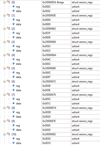
    This is the data I write 

    after stream on I read the datas and they are the same with the init data. Seems normal.


  • Hello, 

    Would you be able to confirm the values of registers 0x4D, 0x4E, 0x55, and 0x56? A complete register dump may be helpful to see how the serializer and deserializer are operating by checking the status registers. Let me know if an example script for register dumps would be needed. 

    Best,

    Zoe