Part Number: SN65LVDS050
Other Parts Discussed in Thread: SN65MLVD040
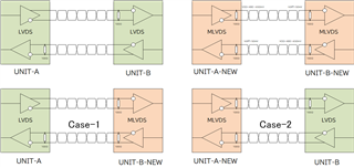
We are currently using LVDS to connect two devices.
It is a point-to-point communication system.
In addition, we are planning to develop a new system.
We are planning to use MLVDS in newly developed systems for several reasons.
In that case, it is necessary to communicate correctly even when the existing system and the new system are combined.
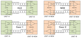
The following combinations can be considered:
In my opinion, we can communicate without any problem.
Distance is 5m, clock speed is 20MHz
Are there any issues with this mixed LVDS and MLVDS system?