This thread has been locked.

If you have a related question, please click the "Ask a related question" button in the top right corner. The newly created question will be automatically linked to this question.

TCAN1145-Q1: Wake up logic

Part Number: TCAN1145-Q1

Hi team,

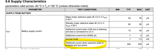
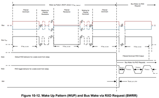
Could you help explain the device wake up logic? When this device get the wake up signal from the system, how can this device wake up MCU? By RX/TX or a specific signal? Could you help show some details? And about the selective mode, how to calculate the total current consumption? What does the additional current mean in the below diagram? And What current  should I add together to get the total current?

  • Hale,

    Could you help explain the device wake up logic?

    This is a partial networking transceiver, so it is capable of selectively waking up only when it detects the proper wake-up frame (WUF) rather than waking up for any wake-up pulse (WUP).

    When this device get the wake up signal from the system, how can this device wake up MCU? By RX/TX or a specific signal? Could you help show some details?

    This is probably best explained using Figure 10-11 in the data sheet. Once the device receives the programmed WUF, it will transition to Standby mode which can activate or power a system similar to most other CAN solutions. This would be externally indicated using INH, which frequently is connected to power supply inputs to activate the node.

    And about the selective mode, how to calculate the total current consumption? What does the additional current mean in the below diagram? And What current  should I add together to get the total current?

    The current consumption in Sleep mode can change depending on the environment. The base current consumption for an idle bus while the device is in Sleep mode is given in line 1 from your snippet above. However, a few things can happen in Sleep mode that alter the current consumption, again best shown in Figure 10-11.

    When communication from other devices begins on the CAN bus, this is interpreted as a WUP, which causes the device to bias the bus to 2.5 V and to activate the SW receiver. These two separate items add additional current consumption on top of the base from line 1, which is given in line 3 and line 6. When the SW receiver is listening and interpreting CAN messages during Sleep mode, then the consumption from line 6 is added to line 1. When there is active communication on the bus, but the device is not intended to wake, this is line 6. When the CAN bus then returns to an idle state at 2.5 V before tSILENCE expires, then line 3 would be added to line 1.

    Best,

    Danny

  • Hi Danny,

    Thanks for your answer.

    Once the device receives the programmed WUF, it will transition to Standby mode which can activate or power a system similar to most other CAN solutions.

    But about your reply, could you explain how our device activate or power a system? The customer replied that they ever tested the RX signal toggle from TJA1145 to activate mcu. But our device seems it has different high and low voltage levels in sleep mode. So the customer didn't know how to activate it. Could you share more details about this progress of activating MCU in sleep mode.

  • Hale,

    In many systems, the INH pin is connected to the EN pin of an LDO or other voltage regulator, a turning on power to the MCU and causing it to activate.

    If a toggle on RXD is needed upon a wake-up, this is configurable. When a bus wake-up occurs, this can be indicated to the MCU using RXD either by a dominant RXD output or by a toggling RXD output:

    I think this might be what they are asking about. The external CAN controller can monitor RXD for transitions to indicate a wake-up in this way. The two different behavior options can be selected at address 12h[2].

    Best,

    Danny