This thread has been locked.

If you have a related question, please click the "Ask a related question" button in the top right corner. The newly created question will be automatically linked to this question.

SN65HVD82: SN65HVD82 related issues

Part Number: SN65HVD82

hi,

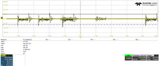
During the operation of SN65HVD82, the dynamic current sending data causes voltage adjustment fluctuations in the isolation power supply, with peak to peak values around 200mV. Will this situation affect communication?  What is the range of power supply fluctuations that will affect communication?

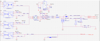
The schematic diagram is as follows:

The fluctuation of power supply is as follows:

Thanks!

  • Are these fluctuations measured at the power supply or at the VCC pin? (C303 will buffer the supply voltage.)

    The range of recommended supply voltages is ±0.5 V, so this is OK. And the required minimum output voltage is only ±1.5 V, so even larger fluctuations should be harmless.

    When in doubt, look at the differential output voltage (tell the oscilloscope to compute A−B).

  • Hi Jeno,

    So Clemens is correct - the C303 will help suppress some of the variation (if not measuring directly at power supply pin of the SN65HVD3082) - regardless it shouldn't cause any real issues as if the nominal voltage is VCC = 5V (which schematic indicates it should be) and 5V +/- 200mV would still put the device in our recommended operational range of  4.5V <= VCC <= 5.5V. 

    You could see some fluctuation of the output differential voltage ( VA - VB) as this voltage is directly sourced from VCC - while there will be some attenuation of the noise from VCC to outputs A or B it may still show up on the bus. However it shouldn't be an issue as the part can maintain the minimum 1.5V between A and B across a 54 Ohm resistor at VCC's as low as 4.5V and worst case from your definition would be 4.8V - so I think risk is extremely minimal. 

    For the schematic itself I have a couple notes

    1. It seems the termination (R379) is DNI - in RS-485 standard both start and end node should be terminated with 120 Ohm resistors with up to +/-10% tolerance. If this is a middle node than its not a big issue. 

    2. The resistors R378 and R380 are very low at only 510 ohms. These can only be placed at 1 node in the system and it limits the max loading of the bus to ~68 nodes.

    Essentially if you short all external power sources and look at the impedance to ground as seen from the "A" pin or the "B" pin (in this analysis the termination is considered DNI) it needs to be >= 375 Ohms. If you place 510 Ohm resistors at 1 node it will limit the max bus loading to ~68 nodes (it is assumed input impedance of SN65HVD3082 is 96k). However if these are placed at 2 or more nodes you will overload the bus and could see potential communication failure. This also assumes none of the other protection devices are loading the bus - they are but it should be minimal compared to transceivers and biasing resistors. 

    If you want this level of biasing on the lines and you want to add resistors to every node I'd suggest sizing the resistors as #nodes * 510. I.e. if your system has 10 nodes and you want to put the resistors on every node then the size would be 5.1k  (510 * 10 nodes).

    However if system is less than 50 to 68 nodes and you only place the 510 ohm resistors on 1 node then the termination on that node will no longer be 120 it will need to be changed to 136 Ohms to properly match the impedance to 120 Ohms when looking into terminated node. 

    Please let me know if you have any other questions!

    Best,

    Parker Dodson