This thread has been locked.

If you have a related question, please click the "Ask a related question" button in the top right corner. The newly created question will be automatically linked to this question.

DP83867E: Power-on timing and reset issues

Part Number: DP83867E

My customer is using DP83867E in their current design.

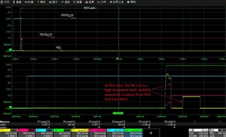
When they use DP83867, MDIO communication failure may occur after power-on (Linux will traverse addresses 0-31). When the communication fails, manually pull RESET_N low and then high, and MDIO communication returns to normal.


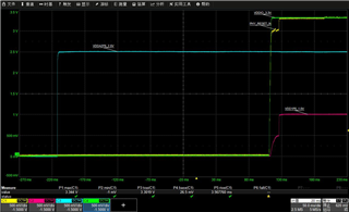
I suspect that the MDIO communication failure is related to the power on reset time duration. Please let us know the power on reset time duration and required power sequencing for the DP83867E PHY.


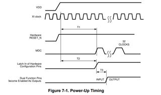
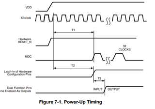
Currently, the PHY uses 3 supply modes (1.0V/2.5V/3.3V). The power-on reset timing diagram is as follows:

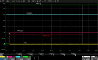
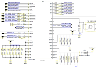
The customer application schematic diagram is as follows:

BR

Adrian

  • Hi Adrian,

    Thank you for sharing the detail information. If possible, could you also probe MDC/MDIO signal relative to VDDA and VDDIO?

    MDC clock signal should come at least 200ms after all the power rail in order to make sure the PHY is operate in the correct mode.

    --

    Thank you,

    Hillman Lin

  • Hi Hillman,

    Thanks for your reply.

    1.The timing of MCD/MDIO relative to VDDA and VDDIO is as following:

    -The MDIO operation will not access phy until uboot is up. There will be almost 8 seconds in between, as shown below:

    -During the power-on process, MDC is pulled up to about 0.9V for a period. This is output by the PHY chip itself, not by the MCU:

    2.In addition, the previous statement needs to be corrected. The customer currently uses Two-Supply Configuration, not Three-Supply Configuration. We did not find the timing requirements in D/S.

    BR

    Adrian

  • Hi Adrian,

    MDC lines should be input only pin for DP83867PHY. I don't think it is possible for MDC to output the voltage. If possible, could you remove the 33 ohms on MDC line and probe the MDC line to see if you still see the pull up on the MDC lines?

    Could you also double check if you have a external pull up resistor on MDIO lines? 

    --

    Thank you,

    Hillman Lin

  • Hi Hillman,

    Samsung tried removing the series resistor on the MDC, but the phenomenon is still the same.


    Can you follow Samsung's power-on timing in a laboratory environment to confirm whether this problem can be reproduced, and whether we have any Reset timing requirements that are not stated in the manual?
    For example, does 3.3V need to be applied after 1.0V? What are the timing requirements for the Reset signal?

    BR

    Adrian

  • HI Adrian

    The Power up sequence in the PHY do have a significant effect on the DP83867PHY. Is adding a reset after power up would be the solution in your system?

    VDD1P0 power rail does not seems to be a clean signal. Is it possible to smooth the slew rate of the traces of VDD1P0 to see if that could prevent the pull up internally on the MDC lines?

    --

    Thank you,

    Hillman Lin

  • Hi Hillman,

    Add a reset after power up can be the solution in customer's system.

    But Samsung wants to know the cause of the probabilistic anomalies in the current power-on sequence. The probability of this problem sometimes exceeds 50%. Because our specifications do not specify the timing requirements?
    Can you provide relevant cause analysis and timing requirements between VDD and Reset?

    BR

    Adrian

  • Hi Adrian,

    Thank you for confirming. Holding reset for 200ms after VDD1P0 power up should be fine in customer application to prevent MDC trigger beforehand.

    --

    Regards,

    Hillman Lin

  • Hi Hillman,

    Thank you for your reply, so what you mean is that for Samsung's current configuration, RESET needs to be applied after VDDA2P5, VDDIO3.3V, VDD1P0 and maintained for more than 200us?

    Can BU explain why the MCD signal jumps before and after VDD1P0 is applied after VDDIO is applied? This helps us beat the 88E1512 on Samsung's project. Can you reproduce it according to Samsung's power-on sequence in the laboratory setup and try to explain the problem? 

    Thank you.

    BR

    Adrian

  • Hi Adrain,

    Holding reset for for 200us after VDD1P0 power up should be fine in customer's application.

    One of the hypothesis that might cause MDC lines to pull up is the bad waveform on VDD1P0.

    --

    Regards,

    Hillman Lin