A related question is a question created from another question. When the related question is created, it will be automatically linked to the original question.
If you have a related question, please click the "Ask a related question" button in the top right corner. The newly created question will be automatically linked to this question.
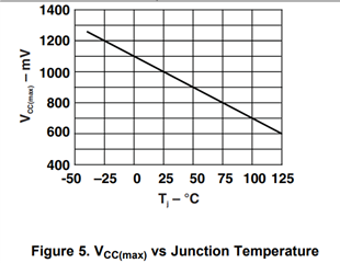
I believe what this graph is trying to communicate is the additional maximum VCC that is allowed above the recommended operating conditions for a given junction temperature Tj.
For example, recommended operating voltage (max) for VCC increases for a lower junction temperature, than if the device has a hotter core temp.
Your understanding seems to be correct, but I am not 100% certain with my answer.
I can't find any additional information that talks about the meaning of this graph in any resource from our team or online. Because it says "VCC(max)" it makes it sound like that a higher junction temperature, the abs. max voltage allotted decreases, but I can't confirm this and don't want to give you wrong information.
My best answer is what you have listed for VCC. I would suspect that at 25C, increasing the recommended operating conditions voltage from 15V to 16V would still maintain the electrical characteristics in the datasheet, but I am not too confident that this is exactly what the graph is saying.
My best recommendation is to stay within the recommended operating conditions regardless, ignoring the graph found in figure 5.