This thread has been locked.

If you have a related question, please click the "Ask a related question" button in the top right corner. The newly created question will be automatically linked to this question.

DS90UB960-Q1: How to configure GPIO output high level for 960 when RX Port Lock fails

Part Number: DS90UB960-Q1

We configure the 0x10 register to 0x81 so that GPIO outputs a high level when the camera is plugged in and a low level when the camera is unplugged.

Now we need to configure the output to be high when the camera is unplugged and low when the camera is plugged in.

How should we configure it

  • Hello,

    Thank you for your question. Programming register 0x10 to 0x81 sets the GPIO0 pin to output the lock status of RX0. Assuming that the camera module includes the serializer as well this means that the pin will be high when lock is achieved and low when lock is not achieved, which aligns with what you've described. Since the GPIO pin is being programmed to output the lock status, it is not possible to reverse the output signal. For most applications the lock status states are sufficient for the system, is there a particular reason why the signal needs to be reversed for your system? If this is a requirement for your system, a software approach could be used to manually program the GPIO0 pin to output a high or low value on the pin based on the reading of the lock status in register 0x4D[0].

    Regards,
    Darrah

  • hi, after I read the lock state in register 0x4D, how do I program the GPIO0 pin to output a high or low level

  • Hello,

    To program GPIO0 to output high set register 0x10 = 0x13, and to set GPIO to output low set register 0x10 = 0x11. Depending on your SOC, different implementations or approaches could be used to generate the same result, but the basic idea is if register 0x4D[0] = 0 (no lock) then the registers to set GPIO0 high will be written, and if register 0x4D[0] = 1 (lock) the registers to set GPIO0 low will be written.

    I'd like to clarify that this specific implementation will be dependent on the frequency that the lock register can be read and will not result in a constant status signal like the lock status output. Even if the system is continuously reading the register and updating the GPIO0 settings, there will still be a delay as the registers are read/written. Although I'm not sure what your system needs or goals are with inverting the signal so this may not be a concern. If a signal that switches with the same frequency as the 0x10 = 0x81 setting is needed, additional logic components like an inverter could be connected to the output of the GPIO0 pin instead.

  • hi

    We now want to configure GPIO0 to be raised when camera 0 has any error. Is this possible?

  • Hello,

    Are you wanting GPIO0 to respond to errors found by the camera or the deserializer? Are there any specific errors that are needed?

    If the camera is the device determining that there is an error, there are two options. First the SoC could read the error/diagnostic registers of the camera and program GPIO0 accordingly. This is similar to the implementation discussed previously, except instead of changing the signal based on lock 0x4D register it would be the corresponding camera registers. The second option would depend on if the camera has a feature to output an error signal on one of its GPIO pins. If the camera can output this signal then that signal can be received on the serializer and transmitted to the 960 to output on GPIO0.

    If the deserializer is the device that identifies the error, the best implementation would depend on what errors are desired to be tracked. GPIO0 can output the pass status of the device. The pass status is an indicator that valid video data is being received. It is possible to program certain errors to be included in the pass status, so that if one of the errors occurs the status will go low until data without any errors is received. Register 0x7D is used to program the pass status and it can include line size, line count, and parity errors. If there are additional errors that you'd like to be included in the GPIO signal, then a more manual implementation similar to what was discussed for lock would be needed. Where instead of reading 0x4D the desired error registers on the deserializer would be read. An additional option would be to program interrupts and use the INTB pin instead of GPIO0.

  • hi, I have another question, I want to know if UB960 has a status register or interrupt signal to indicate the end of a frame

  • Hello,

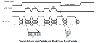
    The 960 does have a frame valid signal that can be output on a GPIO pin. The image below illustrates how the signal corresponds to the CSI data. Another option for monitoring frames would be the frame count registers (0x90 and 0x91). Each time a frame is received on the CSI port the frame count registers will increment.