Part Number: TCA9535
Hi team,
Let me ask you a few questions.
If I set only one input port and all the other ports as outputs, do the INT pins change in conjunction with the input changes?
If this is correct, does it work all the time with no problem as long as I don't go read the register?
Also, if there is a power outage that does not cause a POR, can the register be rewritten and it will work fine?
Is there a possibility of data corruption if POR is not applied?
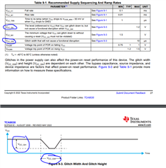
The operation of the INT pin has a maximum delay of 4μs. Does this depend on the speed of SCL?
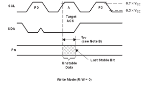
What does "Unstable data" mean in the "Write mode" section on p. 13 of the datasheet?
Does it mean that writing is disabled during ACK?
Best,
Ryu.