Part Number: MAX3232E
Other Parts Discussed in Thread: MAX3232
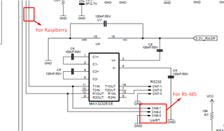
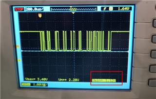
We are facing a problem in a recent assembly batch of item MAX3232E, where, in the current batch, an external module is unable to lower the voltage to LOW on the TX line, causing communication failure.
When replacing the MAX3232E with another from another batch, the failure no longer occurs.
NOK item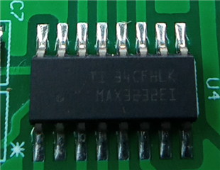
OK item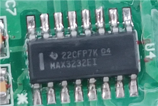
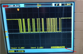
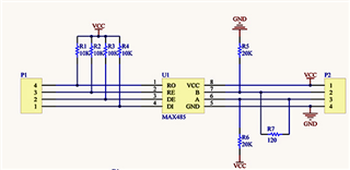
Apparently the MAX3232E output current at pin 12 is higher in this batch, which prevents the RS-485 module from lowering the voltage to an acceptable level for LOW recognition.