This thread has been locked.

If you have a related question, please click the "Ask a related question" button in the top right corner. The newly created question will be automatically linked to this question.

DP83869EVM: Link Loss Pass-Through anomaly

Part Number: DP83869EVM
Other Parts Discussed in Thread: USB-2-MDIO

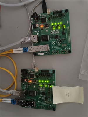
I have the following setup involving two Evaulation Boards DP83869EVM that I want to use in Media Convertor mode:

[Network] - [DP83869EVM + SFP] - [FO] - [DP83869EVM + SFP] - [Computer]

I want to verify the Link Loss Pass-Through feature in both 100Mb and 1000Mb Media Convertor modes.

In both modes, I get the following anomalous behavior:

  1. Everything Connected: All 3 LEDs on both boards light up, link is established, Computer recognizes access to Network, and data transfer at speed is working.
  2. Unplug RJ45 cable from Network-side DP83869EVM: All LEDs turn off, link is broken, Computer reports "network cable unplugged". So far OK.
  3. Plug back in RJ45 cable from Network-side DP83869EVM: All 3 LEDs from Network-side DP83869EVM light up. LED LINK from Computer-side DP83869EVM does not light up, other two LEDs do light up. Computer says Unidentified Network

Step 3 happens only sometimes. I would say 1 every 10 times. Once in the "anomalous" state, if I unplug and replug RJ45 again it will work.

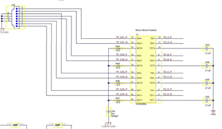
Configuration is only done via Straps:

  • MIRROR_EN: 1
  • OPMODE_2: 1
  • OPMODE_1: 0
  • OPMODE_0: 1/0 depending on speed. As I said, in both cases the behaviour is the same
  • LINK_LOSS: 0 (Enabled)
  • ANEG_DIS: 0
  • ANEGSEL_0: 0
  • ANEGSEL_1: 0
  • ANEGSEL_2: 0

Any help on this matter?

Thank you

  • Hi Esteve,

    Are you able to read the register 0x0000 to 0x001F and 0x006E for all three stage.

    --

    Regards,

    Hillman Lin

  • Good morning, Hillman.

    The table below summarizes the registers you requested of both evauation boards at each step of the process I described. Step 3 in this case went into the "faulty" state.

    Thank you

    Network-side DP83869EVM Computer-side DP83869EVM
    step 1 2 3 1 2 3
    Register 0000 is: 1140 Register 0000 is: 1140 Register 0000 is: 1140 Register 0000 is: 1140 Register 0000 is: 1140 Register 0000 is: 1140
    Register 0001 is: 7969 Register 0001 is: 7949 Register 0001 is: 7969 Register 0001 is: 7969 Register 0001 is: 7969 Register 0001 is: 7969
    Register 0002 is: 2000 Register 0002 is: 2000 Register 0002 is: 2000 Register 0002 is: 2000 Register 0002 is: 2000 Register 0002 is: 2000
    Register 0003 is: A0F3 Register 0003 is: A0F3 Register 0003 is: A0F3 Register 0003 is: A0F3 Register 0003 is: A0F3 Register 0003 is: A0F3
    Register 0004 is: 0181 Register 0004 is: 0181 Register 0004 is: 0181 Register 0004 is: 0181 Register 0004 is: 0181 Register 0004 is: 0181
    Register 0005 is: CDE1 Register 0005 is: 0000 Register 0005 is: CDE1 Register 0005 is: CDE1 Register 0005 is: CDE1 Register 0005 is: CDE1
    Register 0006 is: 006F Register 0006 is: 0064 Register 0006 is: 006F Register 0006 is: 006F Register 0006 is: 006F Register 0006 is: 006F
    Register 0007 is: 2001 Register 0007 is: 2001 Register 0007 is: 2001 Register 0007 is: 2001 Register 0007 is: 2001 Register 0007 is: 2001
    Register 0008 is: 6001 Register 0008 is: 0000 Register 0008 is: 6001 Register 0008 is: 5006 Register 0008 is: 5006 Register 0008 is: 7001
    Register 0009 is: 0300 Register 0009 is: 0300 Register 0009 is: 0300 Register 0009 is: 0300 Register 0009 is: 0300 Register 0009 is: 0300
    Register 000A is: 3800 Register 000A is: 0000 Register 000A is: 3800 Register 000A is: 7800 Register 000A is: 7800 Register 000A is: 0000
    Register 000B is: 0000 Register 000B is: 0000 Register 000B is: 0000 Register 000B is: 0000 Register 000B is: 0000 Register 000B is: 0000
    Register 000C is: 0000 Register 000C is: 0000 Register 000C is: 0000 Register 000C is: 0000 Register 000C is: 0000 Register 000C is: 0000
    Register 000D is: 0000 Register 000D is: 0000 Register 000D is: 0000 Register 000D is: 0000 Register 000D is: 0000 Register 000D is: 0000
    Register 000E is: 0000 Register 000E is: 0000 Register 000E is: 0000 Register 000E is: 0000 Register 000E is: 0000 Register 000E is: 0000
    Register 000F is: F000 Register 000F is: F000 Register 000F is: F000 Register 000F is: F000 Register 000F is: F000 Register 000F is: F000
    Register 0010 is: 5048 Register 0010 is: 5048 Register 0010 is: 5048 Register 0010 is: 5048 Register 0010 is: 5048 Register 0010 is: 5048
    Register 0011 is: BF02 Register 0011 is: 0302 Register 0011 is: BF02 Register 0011 is: BF02 Register 0011 is: BF02 Register 0011 is: 7802
    Register 0012 is: 0000 Register 0012 is: 0000 Register 0012 is: 0000 Register 0012 is: 0000 Register 0012 is: 0000 Register 0012 is: 0000
    Register 0013 is: 1C42 Register 0013 is: 0540 Register 0013 is: 1DC2 Register 0013 is: 1D42 Register 0013 is: 1D42 Register 0013 is: 9C42
    Register 0014 is: 29C7 Register 0014 is: 29C7 Register 0014 is: 29C7 Register 0014 is: 29C7 Register 0014 is: 29C7 Register 0014 is: 29C7
    Register 0015 is: 0003 Register 0015 is: 0003 Register 0015 is: 0003 Register 0015 is: 0000 Register 0015 is: 0000 Register 0015 is: 0000
    Register 0016 is: 0000 Register 0016 is: 0000 Register 0016 is: 0000 Register 0016 is: 0000 Register 0016 is: 0000 Register 0016 is: 0000
    Register 0017 is: 0040 Register 0017 is: 0040 Register 0017 is: 0040 Register 0017 is: 0040 Register 0017 is: 0040 Register 0017 is: 0040
    Register 0018 is: 6150 Register 0018 is: 6150 Register 0018 is: 6150 Register 0018 is: 6150 Register 0018 is: 6150 Register 0018 is: 6150
    Register 0019 is: 4444 Register 0019 is: 4444 Register 0019 is: 4444 Register 0019 is: 4444 Register 0019 is: 4444 Register 0019 is: 4444
    Register 001A is: 0002 Register 001A is: 0002 Register 001A is: 0002 Register 001A is: 0002 Register 001A is: 0002 Register 001A is: 0002
    Register 001B is: 0000 Register 001B is: 0000 Register 001B is: 0000 Register 001B is: 0000 Register 001B is: 0000 Register 001B is: 0000
    Register 001C is: 0000 Register 001C is: 0000 Register 001C is: 0000 Register 001C is: 0000 Register 001C is: 0000 Register 001C is: 0000
    Register 001D is: 0000 Register 001D is: 0000 Register 001D is: 0000 Register 001D is: 0000 Register 001D is: 0000 Register 001D is: 0000
    Register 001E is: 0012 Register 001E is: 0012 Register 001E is: 0012 Register 001E is: 0012 Register 001E is: 0012 Register 001E is: 0012
    Register 001F is: 0000 Register 001F is: 0000 Register 001F is: 0000 Register 001F is: 0000 Register 001F is: 0000 Register 001F is: 0000
    Register 006E is: 0000 Register 006E is: 0000 Register 006E is: 0000 Register 006E is: 0000 Register 006E is: 0000 Register 006E is: 0000
  • Hi Esteve,

    We will discuss with the team internally and get back to you later this week.

    --

    Regards,

    Hillman lin

  • Hi Esteve,

    From the register dump, I did not see any link up in any scenario. Are you not able to perform a link up in any other case.

    --

    Regards,

    Hillman Lin

  • link up

    Good morning,

    In scenario 1, I have re-read the registers of both boards using USB-2-MDIO and bit LINK_STS1 in register 0001h is 0 in both boards indeed (Register value is 7969h).

    However, all LEDs on both boards are lit, as you can see below, and I am able to connect to the internet from my computer, perform speed test, etc.

    Regards

  • Hi Esteve, 

    Based on the LED indication, it seems like your DP83869EVM is link up properly but your register is giving you an link down stage. 

    Could you try to unplug the fiber connection and only connect RJ45 of two EVM together and read register 0x0001 multiple times and see if you are having a link up? Make sure the RJ45 are connected with each other when you are reading the register.

    --

    Regards,

    Hillman Lin

  • Good morning,

    Keep in mind that LNK_LOSS strap is disabled in both boards (Link Loss detection Enabled)

    In this case, With the two boards connected only via RJ45 and both SFP modules removed, register 0001h always reads 7949h (bit LINK_STS1 is 0). I have tried resetting the boards and replugging RJ45 several times but the result is always the same.

    If I enable LNK_LOSS strap and repeat the process, register 0001h reads 7969h. AUTONEG_COMP = 1 is the only bit that changes. But LINK_STS1 still is 0. In this case, only the Link LED is enabled in both boards.

    If I also unplug the RJ45 (only power supply connected. no RJ45. no SFP), the register also reads 7949h

    Is it possible for you to try this on your side?

    Thank you for the assistance.

  • Hello,

    Hillman is OoO today, and will look to respond on Monday when he returns.

    Sincerely,

    Gerome

  • Hi Esteve,

    We try it on our side and we are able to always get a link up between two DP83869EVM. 

    From register 0x006E it seems like you are always in RGMII to copper mode that means your copper should have a link up. If you want to configure DP83869PHY into fiber to copper mode. it could program through register 0x10DF

    May I ask have you done any board modification? If so, may I ask which resistor or components did you depopulate on DP83869ERVM boards?

    Have you follow the userguide document?

    https://www.ti.com/lit/ug/snlu237/snlu237.pdf?ts=1702925524161&ref_url=https%253A%252F%252Fwww.ti.com%252Ftool%252FDP83869EVM

    Is everything over here populated:

    --

    Regards,

    Hillman Lin

  • Good morning,

    I must have been doing something wrong the other day because today I am able to read Link Up in register 0001h. Allow me to upload the register dump again so you can see. Behavior of steps 1, 2 and 3 is the same.

    Network-side DP83869EVM Computer-side DP83869EVM
    step 1 2 3 1 2 3
    Register 0000 is: 1140 Register 0000 is: 1140 Register 0000 is: 1140 Register 0000 is: 1140 Register 0000 is: 1140 Register 0000 is: 1140
    Register 0001 is: 796D Register 0001 is: 7949 Register 0001 is: 796D Register 0001 is: 796D Register 0001 is: 7949 Register 0001 is: 7969
    Register 0002 is: 2000 Register 0002 is: 2000 Register 0002 is: 2000 Register 0002 is: 2000 Register 0002 is: 2000 Register 0002 is: 2000
    Register 0003 is: A0F3 Register 0003 is: A0F3 Register 0003 is: A0F3 Register 0003 is: A0F3 Register 0003 is: A0F3 Register 0003 is: A0F3
    Register 0004 is: 0181 Register 0004 is: 0181 Register 0004 is: 0181 Register 0004 is: 0181 Register 0004 is: 0181 Register 0004 is: 0181
    Register 0005 is: CDE1 Register 0005 is: 0000 Register 0005 is: CDE1 Register 0005 is: CDE1 Register 0005 is: 0000 Register 0005 is: 4DE1
    Register 0006 is: 006F Register 0006 is: 0064 Register 0006 is: 006F Register 0006 is: 006F Register 0006 is: 0066 Register 0006 is: 0067
    Register 0007 is: 2001 Register 0007 is: 2001 Register 0007 is: 2001 Register 0007 is: 2001 Register 0007 is: 2001 Register 0007 is: 2001
    Register 0008 is: 6001 Register 0008 is: 0000 Register 0008 is: 6001 Register 0008 is: 6001 Register 0008 is: 0000 Register 0008 is: 0000
    Register 0009 is: 0300 Register 0009 is: 0300 Register 0009 is: 0300 Register 0009 is: 0300 Register 0009 is: 0300 Register 0009 is: 0300
    Register 000A is: 3800 Register 000A is: 0000 Register 000A is: 3800 Register 000A is: 3800 Register 000A is: 0000 Register 000A is: 0000
    Register 000B is: 0000 Register 000B is: 0000 Register 000B is: 0000 Register 000B is: 0000 Register 000B is: 0000 Register 000B is: 0000
    Register 000C is: 0000 Register 000C is: 0000 Register 000C is: 0000 Register 000C is: 0000 Register 000C is: 0000 Register 000C is: 0000
    Register 000D is: 0000 Register 000D is: 0000 Register 000D is: 0000 Register 000D is: 0000 Register 000D is: 0000 Register 000D is: 0000
    Register 000E is: 0000 Register 000E is: 0000 Register 000E is: 0000 Register 000E is: 0000 Register 000E is: 0000 Register 000E is: 0000
    Register 000F is: F000 Register 000F is: F000 Register 000F is: F000 Register 000F is: F000 Register 000F is: F000 Register 000F is: F000
    Register 0010 is: 5048 Register 0010 is: 5048 Register 0010 is: 5048 Register 0010 is: 5048 Register 0010 is: 5048 Register 0010 is: 5048
    Register 0011 is: BC02 Register 0011 is: 0002 Register 0011 is: BC02 Register 0011 is: BF02 Register 0011 is: 1000 Register 0011 is: 7802
    Register 0012 is: 0000 Register 0012 is: 0000 Register 0012 is: 0000 Register 0012 is: 0000 Register 0012 is: 0000 Register 0012 is: 0000
    Register 0013 is: 1C42 Register 0013 is: 0540 Register 0013 is: 1C42 Register 0013 is: 1C42 Register 0013 is: 1442 Register 0013 is: 1D42
    Register 0014 is: 29C7 Register 0014 is: 29C7 Register 0014 is: 29C7 Register 0014 is: 29C7 Register 0014 is: 29C7 Register 0014 is: 29C7
    Register 0015 is: 0000 Register 0015 is: 0000 Register 0015 is: 0000 Register 0015 is: 0000 Register 0015 is: 0000 Register 0015 is: 0000
    Register 0016 is: 0000 Register 0016 is: 0000 Register 0016 is: 0000 Register 0016 is: 0000 Register 0016 is: 0000 Register 0016 is: 0000
    Register 0017 is: 0040 Register 0017 is: 0040 Register 0017 is: 0040 Register 0017 is: 0040 Register 0017 is: 0040 Register 0017 is: 0040
    Register 0018 is: 6150 Register 0018 is: 6150 Register 0018 is: 6150 Register 0018 is: 6150 Register 0018 is: 6150 Register 0018 is: 6150
    Register 0019 is: 4444 Register 0019 is: 4444 Register 0019 is: 4444 Register 0019 is: 4444 Register 0019 is: 4444 Register 0019 is: 4444
    Register 001A is: 0002 Register 001A is: 0002 Register 001A is: 0002 Register 001A is: 0002 Register 001A is: 0002 Register 001A is: 0002
    Register 001B is: 0000 Register 001B is: 0000 Register 001B is: 0000 Register 001B is: 0000 Register 001B is: 0000 Register 001B is: 0000
    Register 001C is: 0000 Register 001C is: 0000 Register 001C is: 0000 Register 001C is: 0000 Register 001C is: 0000 Register 001C is: 0000
    Register 001D is: 0000 Register 001D is: 0000 Register 001D is: 0000 Register 001D is: 0000 Register 001D is: 0000 Register 001D is: 0000
    Register 001E is: 0012 Register 001E is: 0012 Register 001E is: 0012 Register 001E is: 0012 Register 001E is: 0012 Register 001E is: 0012
    Register 001F is: 0000 Register 001F is: 0000 Register 001F is: 0000 Register 001F is: 0000 Register 001F is: 0000 Register 001F is: 0000
    Register 006E is: 0000 Register 006E is: 0000 Register 006E is: 0000 Register 006E is: 0000 Register 006E is: 0000 Register 006E is: 0000

    As you can see, in step 1 Link is up in both boards, in step 2 Link is up in none of them and in step 3 Link is up only in the Network-side DP83869EVM.

    It is indeed strange that register 006Eh is 0000h because my strap jumpers are configured like this (same as the first time I shared this info):

    • MIRROR_EN: 1 (Jumper installed)
    • OPMODE_2: 1 (Jumper installed)
    • OPMODE_1: 0 (Jumper removed)
    • OPMODE_0: 0 (Jumper removed) (1000Base-T to 1000Base-X)
    • LINK_LOSS: 0 (Jumper removed) (Enabled)
    • ANEG_DIS / LED_0: 0 (Jumper installed in positions 1-2)
    • ANEGSEL_0 / LED_1: 0 (Jumper installed in positions 1-2)
    • ANEGSEL_1 / LED_2: 0 (Jumper installed in positions 1-2)

    Yes, I have followed the user guide.

    Regarding components that I have removed, I have removed none from the picture you attached.

    I have performed the following modifications on the Network-side DP83869EVM (The other one is as it came):

    I have removed R74, R81, R90 and R92, all of them related to the JTAG pins. Since I could not find any documentation on what was the purpose of these resistors, I tried removing them. I think that the behaviour was the same before removing them, but I can put them back and try again.

    I have also bypassed R80 because it is the only way the Reset switch can work, otherwise the Reset pin upon pressing the switch is not pulled down properly. To me, this resistor looks incorrect from a design point of view...

    Thank you once again for your help

  • Hi Esteve,

    Thank you for sharing the correction. Just want to clarify, what is the different between step 1,2, and 3? Because we are seeing a link drop and link back up scenario.

    The schematic modification looks good to me.

    --

    Regards,

    Hillman Lin

  • Hello,

    Step 1: All cables plugged, fiber connected, Status Register in both boards reads Link Up and computer can access the network. (EXPECTED BEHAVIOR)

    Step 2: I unplug the RJ45 cable from the Network-side DP83869EVM. Here, since LNK_LOSS is Enabled in both boards, all 3 LEDs on both boards go dark, computer reports Network Cable Unplugged and from both boards you can read Link Down in Status Register 0001h. (EXPECTED BEHAVIOR)

    Step 3: Now, when plugging back in the RJ45, SOMETIMES, the link does not recover and the system gets into this state: Network-side DP83869EVM has all 3 LEDs on, Status Register 0001h reports Link Up. Computer-side DP83869EVM has the Link LED off and the other two on, Status Register reports Link Down. Computer reports "Network Unrecognized". Here, one board has Link Up and the other one has Link Down (UNEXPECTED BEHAVIOR)

    Once in step 3, if I unplug the RJ45 cable and plug it back in, the link will be established correctly and the situation will be the same as in step 1.

    As I said, the situation in Step 3 only happens sometimes. I would say 1 every 15 times I repeat the process of plugging Network-side DP83869EVM RJ45 cable.

    We also have the situation that Register 006Eh is reading 0000h regardless of the jumpers being installed in the positiones mentioned in my previous post...

    Hope this helps.

    Esteve Cruanyes

  • Hi Esteve,

    Thank you for the clarification. I understand the situation fully right now. The problem occur when you plug and unplug the cable between DP83869EVM to computer.

    Based on register 0x0009, it seems like computer no longer advertise or support 1000Base-T Full duplex and Half Duplex when you unplug and plug in the cable. Could you also double check on the status on the computer on why they are no longer support 1000Base-T when you unplug and plug the cable?

    This should be the root cause of why you are not able to see the link up

    --

    Thank you,

    Hillman Lin

  • Hello,

    No, this is not what I described. The problem occurs when I unplug and plug the cable between the Network and the DP83869EVM.

    Sorry, I don't understand what you are saying about register 0009h. In all cases, its value is 0300h. Looking at the documentation on this register, I can see that bits 8 and 9 (both set to 1) means advertise 1000Base-T.

    It also says that the value of these bits correspond to the setting of straps ANEG_DIS, ANEGSEL_0 and ANEGSEL_1. As I mentioned, theses straps are all set to 0. Acording to this, 1000/100 should be advertised:

    Thanks

  • Hello,

    Hillman is OoO and will be returning on Wednesday 12/27.

    Sincerely,

    Gerome

  • Hi Esteve,

    Sorry for the confusion. I mean register 0x000A indicate that PC does not support 1000BaseT for Computer and DP83869EVM step 3. DP83869EVM do support 1000BaseT in step 3 scenario but not on the PC side.

    Could you check PC status during step 3 scenario?

    --

    Regards,

    Hillman Lin

  • Good morning, Hillman.

    Sorry I could not answer earlier, I was out of office too.

    I have just tried this and when in scenario 3, computer reports this state on the network connection:

    Again, this only happens sometimes. I might need to unplug and replug network-side RJ45 maybe 30 times until scenario 3 happens. Otherwise funcionality is normal and as expected.

    If it is a problem of the computer, what other set-up do you suggest to perform a Link Loss Pass-Through test to validate its functionality?

    Thank you

  • Hi Esteve,

    Thank you for confirming. Did you have any packets generator to check throughput other than laptop? Or did you see the similar scenario with different laptop?

    --

    Regards,

    Hillman Lin