This thread has been locked.

If you have a related question, please click the "Ask a related question" button in the top right corner. The newly created question will be automatically linked to this question.

sn65dsi86 DSIA clock

Other Parts Discussed in Thread: SN65DSI86

HI,

I have a sn65dsi86 EVB connected to an im8mp EVB.

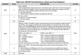
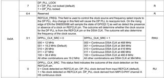
I'm trying to use the mipi_dsi clock (DPPLL_CLK_SRC = 1).

not getting any errors on boot but the display fails to init.

when using a "refclk" which I defined with a 27M clock the display and bridge work fine (no refclk on the target board so its not an option).

dts nodes:

mipi_dsi: mipi_dsi@32e60000 {
                                #address-cells = <1>;
                                #size-cells = <0>;
                                compatible = "fsl,imx8mp-mipi-dsim";
                                #clock-cells = <1>;
                                reg = <0x32e60000 0x10000>;
                                clocks = <&media_blk_ctrl IMX8MP_CLK_MEDIA_BLK_CTRL_MIPI_DSI_PCLK>,
                                         <&media_blk_ctrl IMX8MP_CLK_MEDIA_BLK_CTRL_MIPI_DSI_CLKREF>,
                                         <&clk IMX8MP_CLK_MEDIA_DISP1_PIX_ROOT>;

                                clock-names = "cfg", "pll-ref", "refclk";
                                assigned-clocks = <&clk IMX8MP_CLK_MEDIA_MIPI_PHY1_REF>;
                                assigned-clock-parents = <&clk IMX8MP_CLK_24M>;
                                assigned-clock-rates = <24000000>;
                                interrupts = <GIC_SPI 18 IRQ_TYPE_LEVEL_HIGH>;
                                power-domains = <&mipi_phy1_pd>;
                                status = "disabled";

                                port@0 {
                                        dsim_from_lcdif: endpoint {
                                                remote-endpoint = <&lcdif_to_dsim>;
                                        };
                                };
                        };


 sn65dsi86: sn65dsi86@2d {
                compatible = "ti,sn65dsi86";
                status = "okay";
                reg = <0x2d>;

                ti,dsi-lanes = <4>;
                max,dsi-channel = <1>;
                ti,dp-lanes = <4>;
                pinctrl-names = "default";
                pinctrl-0 = <&pinctrl_mipi_dsi_en>;

                gpio-controller;
                #gpio-cells = <2>;
                #pwm-cells = <1>;

                enable-gpios = <&gpio1 8 GPIO_ACTIVE_HIGH>;
                dsi-clocks;
                clocks = <&clk IMX8MP_CLK_MEDIA_MIPI_PHY1_REF>;
                //clocks = <&mipi_dsi 0>;
                //clock-names = "refclk";

                no-hpd;

                ports {
                        #address-cells = <1>;
                        #size-cells = <0>;
                        port@0 {
                                reg = <0>;
                                sn65dsi86_in: endpoint {
                                        remote-endpoint = <&dsi0_out>;
                                };
                        };
                };
        };
};

please assist,

thanks!

  • It seems that there is some issue with the register settings for the DSI clock division. Have you used the DSI register calculator tool?

    Its linked in the following e2e link: https://e2e.ti.com/support/interface-group/interface/f/interface-forum/945404/faq-sn65dsi86-how-do-i-programming-the-sn65dsi86-registers?tisearch=e2e-sitesearch&keymatch=sn65dsi86

    There should some form of error flagged. Could you check registers 0xF0 - 0xF8 when the display is blank and not working. 

    Also try to get an internal color bar to display while using the DSI clock. This will help further isolate this issue.

  • HI ,

    I used the register calculator in the first place to get the display to work with the refclk.

    is there a parameter in this calculator that should be changed when using the DSI clock? 

    I can only get the register values after removing the bridge's kernel module:

    f0: 03 2f 00 00 01 00 42 01 01 00 00 00 00 00 00 00

    does the bridge know to access the dsi clk on its own or should it be passed to its dts node like i tried to do in the above example?

    im not at all sure about the dts configuration regarding the DSI clock - do u have an example node for this case?

    im currently working on kernel 5.10.

    thanks,

  • The register to make sure you're using the DSI clock is register 0x0A

    Additionally we have a sample Linux driver, but we do not support any software, and anything provided is as is. 

    Here is the link to the driver: https://git.kernel.org/pub/scm/linux/kernel/git/torvalds/linux.git/tree/drivers/video/omap2/dss/dsi.c?id=c16fa4f2ad19908a47c63d8fa436a1178438c7e7

    Please have a look at table 8.31 in the datasheet to debug your errors. 

    It seems that the aux training completes successfully, but no data is sent. 

  • thanks,

    I've set the bridge to use the refclk on our target board but getting no color bar on the test.

    this is the panel edid:

    00 ff ff ff ff ff ff 00 06 af a0 fe 00 00 00 00
    0b 1e 01 04 95 1f 11 78 02 fa 95 92 56 5a 92 2a
    20 50 54 00 00 00 01 01 01 01 01 01 01 01 01 01
    01 01 01 01 01 01 14 37 80 b8 70 38 24 40 10 10
    3e 00 35 ae 10 00 00 1a 10 2c 80 b8 70 38 24 40
    10 10 3e 00 35 ae 10 00 00 1a 00 00 00 fe 00 52
    48 30 44 31 80 42 31 34 30 48 41 4e 00 00 00 00
    00 00 81 21 99 00 11 00 00 0b 01 0a 20 20 00 f3

    the output ASSR script from the register calculator (translated to bash):

    root:~# cat ./i2cset_ASSR_auo.sh

    #REFCLK Frequency #
    i2cset -y 1 0x2c 0x0A 0x0

    #DSI Mode #
    i2cset -y 1 0x2c 0x10 0x26

    #DSIA Clock #
    i2cset -y 1 0x2c 0x12 0x3F

    #DSIB Clock #
    i2cset -y 1 0x2c 0x13 0x3F

    #DP Datarate #
    i2cset -y 1 0x2c 0x94 0x20

    #Enable PLL #
    i2cset -y 1 0x2c 0x0D 0x1
    msleep 10

    #Enable ASSR in Panel #
    i2cset -y 1 0x2c 0x64 0x1
    i2cset -y 1 0x2c 0x74 0x0
    i2cset -y 1 0x2c 0x75 0x1
    i2cset -y 1 0x2c 0x76 0x0a
    i2cset -y 1 0x2c 0x77 0x1
    i2cset -y 1 0x2c 0x78 0x81
    msleep 10

    #Enable enhanced frame and ASSR in DSI86 #
    i2cset -y 1 0x2c 0x5A 0x5

    #Number of DP lanes #
    i2cset -y 1 0x2c 0x93 0x20

    #Start Semi-Auto Link Training #
    i2cset -y 1 0x2c 0x96 0x0A

    msleep 10
    #CHA Active Line Length #
    i2cset -y 1 0x2c 0x20 0x80
    i2cset -y 1 0x2c 0x21 0x07

    #CHB Active Line Length #
    i2cset -y 1 0x2c 0x22 0x0
    i2cset -y 1 0x2c 0x23 0x0

    #Vertical Active Size #
    i2cset -y 1 0x2c 0x24 0x38
    i2cset -y 1 0x2c 0x25 0x04

    #Horizontal Pulse Width #
    i2cset -y 1 0x2c 0x2C 0x10
    i2cset -y 1 0x2c 0x2d 0x00

    #Vertical Pulse Width #
    i2cset -y 1 0x2c 0x30 0x14
    i2cset -y 1 0x2c 0x31 0x00

    #HBP #
    i2cset -y 1 0x2c 0x34 0x98

    #VBP #
    i2cset -y 1 0x2c 0x36 0x0D

    #===== HFP #
    i2cset -y 1 0x2c 0x38 0x10

    #===== VFP #
    i2cset -y 1 0x2c 0x3A 0x03

    #===== DP-18BPP Disable #
    i2cset -y 1 0x2c 0x5B 0x0

    #===== Color Bar Enable #
    i2cset -y 1 0x2c 0x3C 0x12

    i2cset -y 1 0x2c 0x5A 0x0D

    #====== backlight enable #

    i2cset -y 1 0x2c 0x5E 0x0A
    i2cset -y 1 0x2c 0x5F 0x44

    can you verify the output please?

  • Hey Shlomi,

    As long as the registers are generated by the excel sheet they should be correct. This script confirmed works on the DSi86 EVM.

    <aardvark>
        <configure i2c="1" spi="1" gpio="0" tpower="1" pullups="1"/>
        <i2c_bitrate khz="100"/>
        
      <i2c_write addr="0x2D" count="1" radix="16">5C 01</i2c_write> <sleep ms="10"/>
    
       <i2c_write addr="0x2D" count="1" radix="16">FF 07</i2c_write> <sleep ms="10"/>
    
    ======DUMP CFR======
       <i2c_write addr="0x2D" count="0" radix="16">16 </i2c_write> <sleep ms="10"/>
    
    ======Read======
        <i2c_read addr="0x2D" count="1" radix="16">00</i2c_read> <sleep ms="10"/>
    
    
       <i2c_write addr="0x2D" count="1" radix="16">16 01</i2c_write> <sleep ms="10"/>
    
       <i2c_write addr="0x2D" count="0" radix="16">16 </i2c_write> <sleep ms="10"/>
    
    ======Read======
        <i2c_read addr="0x2D" count="2" radix="16">00</i2c_read> <sleep ms="10"/>
    
      <i2c_write addr="0x2D" count="1" radix="16">FF 00</i2c_write> <sleep ms="10"/>
    
    
    ======Single 4 DSI lanes======
    
      <i2c_write addr="0x2D" count="1" radix="16">10 26 </i2c_write> <sleep ms="10"/>
    
    ======DSI CLK FREQ======
    
      <i2c_write addr="0x2D" count="0" radix="16">12 </i2c_write> <sleep ms="10"/>
       <i2c_read addr="0x2D" count="2" radix="16">00</i2c_read> <sleep ms="10"/>


    ======enhanced framing======
    
      <i2c_write addr="0x2D" count="1" radix="16">5A 04 </i2c_write> <sleep ms="10"/>
    
    
    ======ADDR 0x93 CFR======
    
       <i2c_write addr="0x2D" count="0" radix="16">93</i2c_write> <sleep ms="10"/>
    
    ======Read======
        <i2c_read addr="0x2D" count="6" radix="16">00</i2c_read> <sleep ms="10"/>
    
    ======Pre0dB 1 lanes no SSC======
       <i2c_write addr="0x2D" count="1" radix="16">93 10</i2c_write> <sleep ms="10"/>
    
    ======L0mV RBR======
       <i2c_write addr="0x2D" count="1" radix="16">94 80</i2c_write> <sleep ms="10"/>
    
    ======POST2 0dB ======
       <i2c_write addr="0x2D" count="1" radix="16">95 00</i2c_write> <sleep ms="10"/>
    
    ======PLL ENABLE======
       <i2c_write addr="0x2D" count="1" radix="16">0D 01</i2c_write> <sleep ms="10"/>
       <i2c_write addr="0x2D" count="0" radix="16">0A</i2c_write> <sleep ms="10"/>
       <i2c_read addr="0x2D" count="2" radix="16">00</i2c_read> <sleep ms="10"/>


    ======Semi-Auto TRAIN ======
       <i2c_write addr="0x2D" count="1" radix="16">96 0A</i2c_write> <sleep ms="20"/>
    
    
    ======ADDR 0x0A CFR======
    
       <i2c_write addr="0x2D" count="0" radix="16">96</i2c_write> <sleep ms="20"/>
    
    ======Read======
        <i2c_read addr="0x2D" count="1" radix="16">00</i2c_read> <sleep ms="10"/>
    
    =====CHA_ACTIVE_LINE_LENGTH=======
        <i2c_write addr="0x2D" count="2" radix="16">20 00 04</i2c_write> <sleep ms="10"/>
    
    =====CHA_VERTICAL_DISPLAY_SIZE=======
        <i2c_write addr="0x2D" count="2" radix="16">24 58 02</i2c_write> <sleep ms="10"/>
    
    =====CHA_SYNC_DELAY=======
        <i2c_write addr="0x2D" count="2" radix="16">28 00 00</i2c_write> <sleep ms="10"/>
    
    =====CHA_HSYNC_PULSE_WIDTH=======
        <i2c_write addr="0x2D" count="2" radix="16">2C 80 80</i2c_write> <sleep ms="10"/>
    
    =====CHA_VSYNC_PULSE_WIDTH=======
        <i2c_write addr="0x2D" count="2" radix="16">30 04 80</i2c_write> <sleep ms="10"/>
    
    =====CHA_HORIZONTAL_BACK_PORCH=======
        <i2c_write addr="0x2D" count="1" radix="16">34 28 </i2c_write> <sleep ms="10"/>
    
    =====CHA_VERTICAL_BACK_PORCH=======
        <i2c_write addr="0x2D" count="1" radix="16">36 09</i2c_write> <sleep ms="10"/>
    
    =====CHA_HORIZONTAL_FRONT_PORCH=======
        <i2c_write addr="0x2D" count="1" radix="16">38 28</i2c_write> <sleep ms="10"/>
    
    =====CHA_VERTICAL_FRONT_PORCH=======
        <i2c_write addr="0x2D" count="1" radix="16">3A 01</i2c_write> <sleep ms="10"/>
    
    =====DP_18BPP_EN =======
      <i2c_write addr="0x2D" count="1" radix="16">5B 01 </i2c_write> <sleep ms="100"/>
    
    =====COLOR BAR =======
        <i2c_write addr="0x2D" count="1" radix="16">3C 10</i2c_write> <sleep ms="100"/>
    
    ======enhanced framing and Vstream enable======
    
      <i2c_write addr="0x2D" count="1" radix="16">5A 0C </i2c_write> <sleep ms="100"/>
    
    ======DUMP CFR======
        <i2c_write addr="0x2D" count="0" radix="16">20</i2c_write> <sleep ms="10"/>
    
    ======Read======
        <i2c_read addr="0x2D" count="32" radix="16">00</i2c_read> <sleep ms="10"/>


    </aardvark>
    

    If you cant get the script to work please have a look at the following debugging guide. 

    Debugging guide: https://e2e.ti.com/support/interface-group/interface/f/interface-forum/945403/faq-sn65dsi86-sn65dsi86-black-screen-debugging-guide?tisearch=e2e-sitesearch&keymatch=sn65dsi86#

  • This script works using an Aardvark I2C controller, but the register values can be extracted from the script. 

  • im getting the following errors:

    root@imx8mp-lpddr4-kazuar:~# i2cdump -y 1 0x2c
    No size specified (using byte-data access)
    0 1 2 3 4 5 6 7 8 9 a b c d e f 0123456789abcdef
    00: 36 38 49 53 44 20 20 20 02 00 80 00 00 01 00 00 68ISD ?.?..?..
    10: 26 00 3f 3f 00 00 00 00 00 00 00 00 00 00 00 00 &.??............
    20: 80 07 00 00 38 04 00 00 00 00 00 00 10 00 00 00 ??..8?......?...
    30: 14 00 00 00 98 00 0d 00 10 00 03 00 12 00 00 00 ?...?.?.?.?.?...
    40: 55 6f 00 00 80 00 38 08 5c 04 a8 00 21 00 10 00 Uo..?.8?\??.!.?.
    50: 14 00 80 07 38 04 20 00 40 e4 0d 00 10 00 ba 44 ?.??8? .@??.?.?D
    60: a0 60 a4 00 00 00 00 00 00 00 00 00 00 00 00 00 ?`?.............
    70: 00 00 00 00 00 01 02 01 80 81 00 00 00 00 00 00 .....?????......
    80: 00 00 00 00 00 00 00 00 00 1f 7c f0 c1 07 1f 7c .........?|????|
    90: f0 c1 07 20 20 00 01 04 01 00 00 00 00 00 00 00 ??? .???.......
    a0: 01 ff ff 00 00 00 00 00 00 00 00 00 00 00 00 00 ?...............
    b0: 04 78 ac ac 08 6c 9c 9c 0c 5c 5c 5c 0c 0c 0c 0c ?x???l???\\\????
    c0: 3f 3f 0f 00 00 00 00 00 00 00 00 00 00 00 00 00 ???.............
    d0: 00 00 00 00 00 00 00 00 00 00 00 00 00 00 00 00 ................
    e0: 00 00 00 00 00 00 00 00 00 00 00 00 00 00 00 00 ................
    f0: 00 00 00 00 01 02 80 00 01 00 00 00 00 00 00 00 ....???.?.......

    0xf6  = 0x80 indicating:

    VIDEO_WIDTH_PROG_ERR. This field is set whenever the video parameters define more bytes of
    pixel data than can be transferred in the allotted video portion of the line time.

    the rerclk is 12Mhz and the default imx8mp mipi_dsi settings haven't been changed.

    is the script you pasted generated from the edid i provided? i don't get any 'read' commands on my generated script.

  • The color bar will be a 800x600 image that should fit within most displays. Works for multiple monitors on our end. When your setup is working are there any errors seen on the DSI86 EVM. The read is simply a double check the the I2c line is operating correctly, part of a script check function. 

    Could you send the spec of your system rather than the EDID and i2c dump? My assumption is that the issue is due to the DSI clock being at a fringe frequency which is causing issue with the PLL

  • imx8mp (kernel 5.15 or 6.1 on yocto langdale) custom board <-> sn65dsi86 <-> edp panel (AUO model RH0D1 (B140han07) )

    ill check the EVM for errors and reply.

  • Another thing id like to confirm is that the end to end system works correctly while using refclk correct. Meaning you are able to use your driver and custom board to send an image through the bridge to the eDp panel. 

  • how do u conduct such a test while the display fails to display a color bar?

    when the driver is loaded I have a framebuffer dev on /dev/fb0 but the display manager (weston) is failing to start.

    I cannot confirm the reason for the weston failure (g2d lib) while the basic i2c test is not working.

  • when using a "refclk" which I defined with a 27M clock the display and bridge work fine

    Does the bridge not work in this case? Because if the only thing you are switching is from ref clock to DSI clock all you need to change are the following registers to your spec:

    0x0A

    0x11

    0x12 & 0x13 

    if these registers are set up correctly there should be no issue in the bridge when transitioning from a working refclk to a DSI clock.

  • it worked when using the EVM with a 27M refclk with an NXP imx8mp EVB. on my custom board I'm not able to get the dsi phy clock as a source (what began this whole thread).

    I'm currently only able to set only a 12M refclk on my board and getting a black screen (no color bar)

  • i managed to get a 27M refclk on my custom board and the display works.

    any idea why it fails on 12M ?

  • What errors are you getting when it fails on the 12M? is the PLL locking?

  • additionally could you send me the datasheet for your panel? I cant find one online for B140han07

  • yes it's locking.

    you can see the errors from the i2c dump i pasted earlier.

    f0: 00 00 00 00 01 02 80 00 01 00 00 00 00 00 00 00 

  • It seems that the line time is incorrect when you use the lower speed. Do you recalculate the registers using the excel sheet to adjust for the lower datarate? It seems that the line time remians at the same speed you use for 27M refclk but your datarate is reduced so there is a timing issue. Please adjust using the spreadsheet.

  • The errors you are getting shouldn't be an issue regarding functionality. 

  • Hi,

    i connected several panels via the TI EVM and one of them shows a black screen.

    i adjusted the driver for each panel so the timing would be correct according to the known edid.

    this is the i2cdump:

    root@sr-imx8-rc:~# i2cdump -y 2 0x2d
    No size specified (using byte-data access)
    0 1 2 3 4 5 6 7 8 9 a b c d e f 0123456789abcdef
    00: 36 38 49 53 44 20 20 20 02 00 86 00 00 01 00 00 68ISD ?.?..?..
    10: 26 00 54 00 00 00 00 00 00 00 00 00 00 00 00 00 &.T.............
    20: 80 07 00 00 38 04 00 00 00 00 00 00 10 00 00 00 ??..8?......?...
    30: 0e 00 00 00 98 00 13 00 10 00 03 00 00 00 00 00 ?...?.?.?.?.....
    40: 83 6b 00 00 80 00 38 08 5c 04 a8 00 21 00 10 00 ?k..?.8?\??.!.?.
    50: 0e 00 80 07 38 04 00 00 40 e4 0d 01 11 00 b0 00 ?.??8?..@????.?.
    60: a0 60 a4 00 00 00 00 00 00 00 00 00 00 00 00 00 ?`?.............
    70: 00 00 00 00 00 01 02 01 80 81 00 00 00 00 00 00 .....?????......
    80: 00 00 00 00 00 00 00 00 00 1f 7c f0 c1 07 1f 7c .........?|????|
    90: f0 c1 07 24 20 00 01 04 01 00 00 00 00 00 00 00 ???$ .???.......
    a0: 01 ff ff 00 00 00 00 00 00 00 00 00 00 00 00 00 ?...............
    b0: 04 78 ac ac 08 6c 9c 9c 0c 5c 5c 5c 0c 0c 0c 0c ?x???l???\\\????
    c0: 3f 3f 0f 00 00 00 00 00 00 00 00 00 00 00 00 00 ???.............
    d0: 00 00 00 00 00 00 00 00 00 00 00 00 00 00 00 00 ................
    e0: 00 00 00 00 00 00 00 00 00 00 00 00 00 00 00 00 ................
    f0: 03 00 00 00 01 00 c2 00 01 00 00 00 00 00 00 00 ?...?.?.?.......

    the driver loads without errors and the fb0 dev is created, also link training seems ok.

    as you can see 0xf6 indicated some dp sync issue but i cant resolve it. 

  • Hey Shlomi,

    Can you send the exact spec of the panel with the black screen? The errors the device is seeing are still synch errors associated with defining more bytes of pixel data than can be transferred in the allotted video portion of the line time, hsync errors, and SOT errors.

  • All of these issues have to do with line time. Can you verify that you are sending the DSI waveform the device is setup to receive via waveform captures. 

  • Hey Shlomi, 

    It seems that the datasheet download is behind a membership/ pay wall. Can you send screenshots of the datasheet with all relevant information on the input parameters?

    Additionally did the line time fix resolve the 12Mhz clock issue?

  • Hi,

    attached is the edid decode with all the required data (this is what I used for the other (working) panels. I don't have the datasheet either.

    I don't have a 12M clk setup to test the change currently but will update once I do.

    root@test0003:/home/user# edid-decode  /sys/devices/pci0000:00/0000:00:02.0/drm/card0/card0-eDP-1/edid
    edid-decode (hex):
    
    00 ff ff ff ff ff ff 00 06 af a0 fe 00 00 00 00
    0b 1e 01 04 95 1f 11 78 02 fa 95 92 56 5a 92 2a
    20 50 54 00 00 00 01 01 01 01 01 01 01 01 01 01
    01 01 01 01 01 01 14 37 80 b8 70 38 24 40 10 10
    3e 00 35 ae 10 00 00 1a 10 2c 80 b8 70 38 24 40
    10 10 3e 00 35 ae 10 00 00 1a 00 00 00 fe 00 52
    48 30 44 31 80 42 31 34 30 48 41 4e 00 00 00 00
    00 00 81 21 99 00 11 00 00 0b 01 0a 20 20 00 f3
    
    ----------------
    
    Block 0, Base EDID:
      EDID Structure Version & Revision: 1.4
      Vendor & Product Identification:
        Manufacturer: AUO
        Model: 65184
        Made in: week 11 of 2020
      Basic Display Parameters & Features:
        Digital display
        Bits per primary color channel: 6
        DisplayPort interface
        Maximum image size: 31 cm x 17 cm
        Gamma: 2.20
        Supported color formats: RGB 4:4:4
        First detailed timing includes the native pixel format and preferred refresh rate
      Color Characteristics:
        Red  : 0.5732, 0.3388
        Green: 0.3535, 0.5722
        Blue : 0.1660, 0.1259
        White: 0.3134, 0.3291
      Established Timings I & II: none
      Standard Timings: none
      Detailed Timing Descriptors:
        DTD 1:  1920x1080   60.049 Hz  16:9    67.015 kHz 141.000 MHz (309 mm x 174 mm)
                     Hfront   16 Hsync  16 Hback 152 Hpol P
                     Vfront    3 Vsync  14 Vback  19 Vpol N
        DTD 2:  1920x1080   48.040 Hz  16:9    53.612 kHz 112.800 MHz (309 mm x 174 mm)
                     Hfront   16 Hsync  16 Hback 152 Hpol P
                     Vfront    3 Vsync  14 Vback  19 Vpol N
        Alphanumeric Data String: 'RH0D1'
        Manufacturer-Specified Display Descriptor (0x00): 00 00 00 00 81 21 99 00 11 00 00 0b 01 0a 20 20 '.....!........  '
    Checksum: 0xf3

  • Based of the EDID looks like the color format is culprit of the problem. This display supports RGB444, but the DSI86 can only support RGB666 and RGB888.

    Datasheet:

    EDID:

  • HI,

    the other panels that work also show rgb 4:4:4 so that may not be the issue, for example:

    root@dl0009-Latitude-5440:/home/dl0009# edid-decode /sys/devices/pci0000:00/0000:00:02.0/drm/card0/card0-eDP-1/edid
    edid-decode (hex):

    00 ff ff ff ff ff ff 00 09 e5 fc 0a 00 00 00 00
    0d 1e 01 04 95 1f 11 78 02 ef 35 95 5d 59 94 2a
    21 50 54 00 00 00 01 01 01 01 01 01 01 01 01 01
    01 01 01 01 01 01 3a 39 80 04 71 38 28 40 30 20
    36 00 35 ae 10 00 00 1a c8 2d 80 04 71 38 28 40
    30 20 36 00 35 ae 10 00 00 1a 00 00 00 fe 00 58
    59 43 30 35 80 4e 56 31 34 4e 34 4e 00 00 00 00
    00 00 41 21 99 00 10 00 00 0a 01 0a 20 20 00 d9

    ----------------

    Block 0, Base EDID:
    EDID Structure Version & Revision: 1.4
    Vendor & Product Identification:
    Manufacturer: BOE
    Model: 2812
    Made in: week 13 of 2020
    Basic Display Parameters & Features:
    Digital display
    Bits per primary color channel: 6
    DisplayPort interface
    Maximum image size: 31 cm x 17 cm
    Gamma: 2.20
    Supported color formats: RGB 4:4:4
    First detailed timing includes the native pixel format and preferred refresh rate
    Color Characteristics:
    Red : 0.5849, 0.3652
    Green: 0.3505, 0.5810
    Blue : 0.1640, 0.1318
    White: 0.3134, 0.3291
    Established Timings I & II: none
    Standard Timings: none
    Detailed Timing Descriptors:
    DTD 1: 1920x1080 60.002 Hz 16:9 67.202 kHz 146.500 MHz (309 mm x 174 mm)
    Hfront 48 Hsync 32 Hback 180 Hpol P
    Vfront 3 Vsync 6 Vback 31 Vpol N
    DTD 2: 1920x1080 48.001 Hz 16:9 53.761 kHz 117.200 MHz (309 mm x 174 mm)
    Hfront 48 Hsync 32 Hback 180 Hpol P
    Vfront 3 Vsync 6 Vback 31 Vpol N
    Alphanumeric Data String: 'XYC05'
    Manufacturer-Specified Display Descriptor (0x00): 00 00 00 00 41 21 99 00 10 00 00 0a 01 0a 20 20 '....A!........ '
    Checksum: 0xd9

  • Interesting, yeah I agree if RGB 4:4:4 works for others this probably isn't the root problem.

    Do you get any errors in the error registers when using the BOE 2812 panel? Additionally are these the only RGB 4:4:4 panels you are using? If so, please contact the manufacturer to verify that the BOE 2812 doesn't have any extended capability, as the DSI86 can only output RGB 6:6:6 and RGB 8:8:8

  • hi,  
    Can you please share me the full dts related to edp interface with imx8mp for reference pls,