This thread has been locked.

If you have a related question, please click the "Ask a related question" button in the top right corner. The newly created question will be automatically linked to this question.

TUSB1002: AC coupling

Part Number: TUSB1002
Other Parts Discussed in Thread: , HD3SS3220

Hi All,

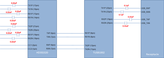
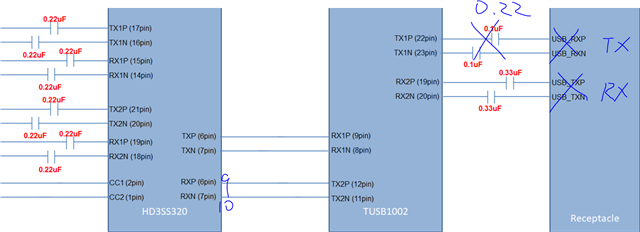
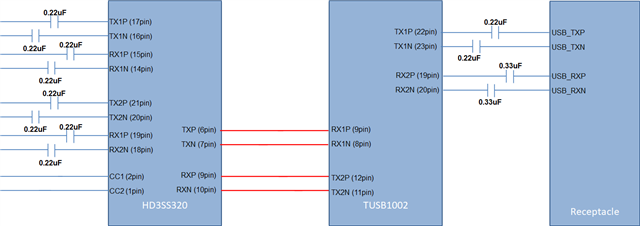
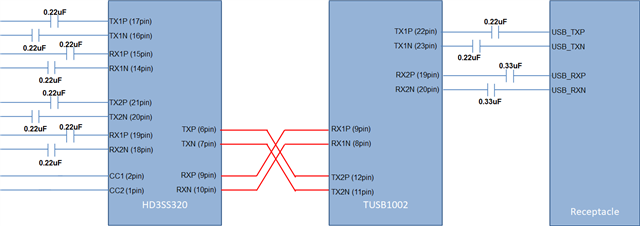
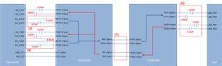
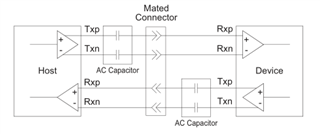
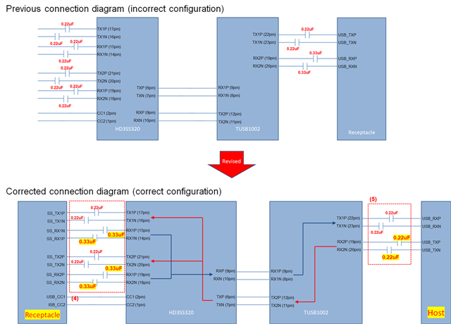
I would like you to check the circuit diagram for AC coupling of TUSB1002.

Set the AC coupling capacitance in the simple circuit diagram below. Is this OK?

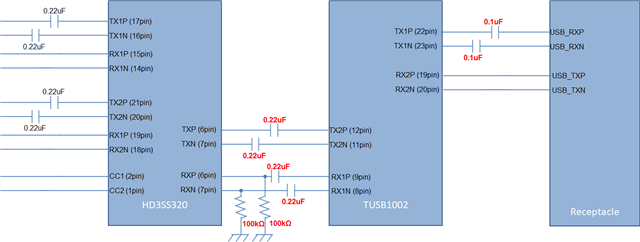
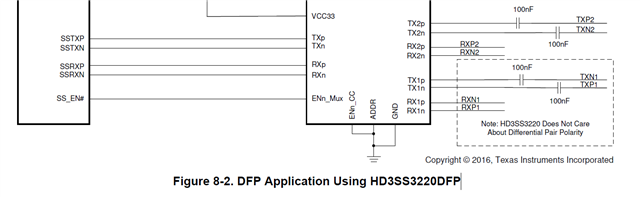
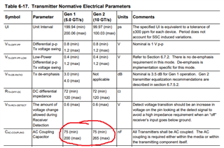
The datasheet has an AC coupling capacitor on the RX line, but the EVM didn't have one on the RX line. which one is correct? Please tell me the recommended capacitor value.

Best Regards,
Ishiwata

  • Ishiwata-san

    1. Please use TUSB1002A instead TUSB1002

    2. Make sure HD3SS3220 RX1 and RX2 are AC coupled, recommend value is 0.22uF

    3. HD3SS3220 and TUSB1002A DC coupled

    4. TUSB1002A RX2 AC coupling is optional. If used, the value is 0.33uF.

    Thanks

    David

  • David-san,

    Thank you very much for your support.

    Based on your advice, I modified the circuit diagram below.

    Is this alright?

    Best Regards,
    Ishiwata

  • Ishiwata-san

    Please see below block diagram.

    Thanks

    David

  • Hi David-san,


    Thank you for your support.

    I have an additional question.
    Which is the correct connection between HD3SS320 and TUSB1002?

    In the HD3SS320 datasheet (Figure 8-2. DFP Application Using HD3SS3220DFP), TXs are connected to each other and RXs are connected to each other.


    Best Regards,
    Ishiwata

  • Hi David-san,

    Thank you for your answer.

    I have an additional question.


    1)
    Please tell me the reason for DC coupling between HD3SS3220 and TUSB1002.
    There is no description of Vdiff and Vcom for TX and RX of HD3SS3220.
    The following electrical characteristics of HD3SS3220 have been confirmed.


    2)
    Please tell me the reason for the asymmetrical capacitance of 0.22uF for TX and 0.33uF for Rx between TUSB1002 and CPU.
    Also, please tell me about the AC capacity. You can understand the 0.33uF of Rx from the recommended circuit in the data sheet.
    Please tell me the reason why you installed Tx at 0.22uF.


    3)
    I have a question about RX between the USB Type-C connector and HD3SS3220.
    You advised me to recommend 0.22uFw for the RX AC coupling capacitor.
    The ECN below recommends 297-363nF.
    /cfs-file/__key/communityserver-discussions-components-files/138/USB-3.1-ECN-Rx-AC-Coupling-Capacitor-Option.pdf 
    Please tell me why you recommend 0.22uF.


    Best Regards,
    Ishiwata

  • Hi Ishiwata-san,

    David is out of the office so I will answer your questions until he returns.

    1. You want to keep the total capacitance on the USB line within the spec for USB. Having capacitors on both sides of the HD3SS3220 could drop the series capacitance below 75nF (the lowest allowable value for USB3 signals). It is ok to DC couple the MUX to the 1002A as the MUX simply connects TX to TX1/2 and RX to RX1/2. Since you have capacitors on TX1/2 and RX1/2, DC coupling to the 1002A is ok.

    2. TX and RX capacitors have different recommended values based on the allowable capacitance of a USB signal line. The USB spec requires that all transmitters (TX) be AC coupled while receiver (RX) capacitors are optional.

    The total capacitance must stay between 75 - 265nF. This includes the capacitor on the TX side and the capacitor on the RX side. Since a transmitter will usually have AC capacitors on the lower end (between 100nF - 220nF), the RX should have a capacitance on the higher end (closer to 330nF). This is so the total capacitance stays above 75nF, as when you add capacitors in series the total capacitance drops. 

    3. Depending on the device plugged in, 220nF or higher RX capacitors could work. For example, if the AC capacitor on the device TX is 220nF, then a 220nF RX capacitor is ok because the total capacitance is still above 75nF. If the device has a lower value capacitor on the transmitter, a higher value RX capacitor would be better (usually 330nF).

    Best,

    Shane

  • Hi Shane-san,

    Thank you for your answer.

    I thought about question 1) further.
    The reason for DC coupling is that when AC coupling is used, the common voltage becomes 0V and negative power is applied.
    At that time, the Absolute Maximum will be exceeded. I think that AC coupling is not possible because of this, but is my understanding correct?

    Best Regards,
    Ishiwata

  • Ishiwata-san

    For question 1, the HD3SS3220 requires a bias voltage, the designer must place the capacitors on one side of the switch. We choose to place the capacitors between the HD3SS3220 and the connector because we can't always guarantee the common mode voltage of the external device connected to the connector meets the bias voltage requirement of HD3SS3220. 

    With the capacitors between HD3SS3220 and the connector, we then choose to DC couple between TUSB1002A and HD3SS3220 so the TUSB1002A common mode voltage would bias the HD3SS3220. The TUSB1002A common mode voltage also meets the HD3SS3220 bias voltage requirement.

    If you choose to place bias resistors on both sides of the switch, an external biasing voltage should be provided. The external biasing voltage must meet HD3SS3220 bias voltage requirement.

    Thanks

    David

  • Hi David-san,

    Thank you for your answer.

    I configured the question incorrectly. When I first asked David-san, I had reversed Host and Receptacle. Correctly, this is the corrected connection diagram.

    Can you confirm again that the AC coupling capacitance value is correct?

    4) On the Receptacle side, Tx is 0.22uF. Rx is 0.33uF from ECN. Is this correct?

    5) Connection with host is 0.22uF for both Tx and Rx. Is this correct?

    Best Regards,
    Ishiwata

  • Ishiwata-san

    The connection looks correct.

    Thanks

    David