This thread has been locked.

If you have a related question, please click the "Ask a related question" button in the top right corner. The newly created question will be automatically linked to this question.

THVD8000: Same board with different THVD8000 cause fail communication

Part Number: THVD8000

Hi Team,

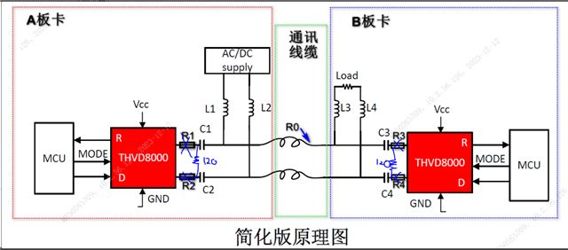
Customer design THVD8000 system like below, where R1=R2=R3=R4=200hm, C1=C2=C3=C4=470nF, L1=L2=L3=L4=10uH. Cable resistance R0=1.9ohm.  Carrier frequency is 5MHz. The detailed schematics I will attach later. 

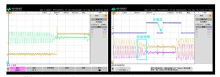
For A board, we got four boards: A1, A2, A3 and A4. When these boards communicate with B board, A1 always success, A2 always fail. others sometimes success. We exchange the chips on A1 and A2 and found that A2 becomes success and A1 become fail. And then we tested the carrier waveform and RX waveform and found that the reflection of the failed one take times to die down which cause the ripples (the right picture). And we are suspecting that's the reason why the communication fail. The left picture is the good waveform for the successful communication.

So the questions are:

1. with same design, why these devices behave different?

2. In THVD8000 design guide, termination resistor can help to settle down the signal quickly. Do you have a guide for how to select the resistance value of termination resistor?

3. If choose a fixed termination resistor, how to guarantee 100% successful communication in production?

Thanks!

Rayna

  • Hi Rayna,

    So I am going to preface by stating a few things that need to be met for proper THVD8000 applications:

    0.1: Needs proper termination on start and end node (if more than 2 nodes - middle nodes are unterminated but should not deviate from main trunk of bus by more than 300mm - daisy chaining is preferred in this case) 

    0.2: Additional attenuation must be removed. R1, R2, R3, and R4 all should be removed. Generally speaking unless its part of larger protection network with external diodes series resistors on RS-485 / THVD8000 only makes your system worse - they are causing a ton of attenuation and reducing the SNR of the signal - which is going to be more likely to cause problems. 

    0.3 The L/C values must be correct. So if customer system is only 2 nodes then the inductors need to be bumped up to around 25uH to 30uH or else you are overloading the bus. Overloading the bus could add additional wear and tear to the THVD8000 + reduce the SNR which could cause issues in communication. 

    1. So both waveforms look kind of messy - and the THVD8000 at 5MHz does not have a lot of noise margin. I have a few questions to help narrow down the potential problems. 

    1a) Can you please share a picture of the top of the units that are failing and one of the units that are okay - I just want to verify that the devices are legitimate.

    1b) How long is the cable between the nodes in the test situation. Is it longer than 300mm? If it is longer than 300mm then reflections at signal transitions are going to start being a problem for systems that are not properly terminated. 

    Customers choice of termination - the series 200 ohm resistors is very much discouraged and inadvisable . The first and last node in the chain should have a 120 ohm resistor between A and B

    Essentially short R1, R2, R3, R4 (i.e. make these equal to 0 ohms - if kept they should be no more than ~10 ohms) and add the 120 ohm resistor in-between A and B pins. This will cut down on reflections pretty greatly because right now its basically reflecting 100% of the incident signal in the current design for systems over 300mm (1ft)  in length.

    So essentially:

    Both waveforms look messy - the reflections seems to be riding the line between okay and problematic. Meaning that both designs could have issues but the issue doesn't occur 100% of the time. 

    Please let me know on the pictures of the "good" units and "suspect" units as well as the bus length.  It is imperative that the bus be properly terminated to mitigate reflections. 

    2. Yes - use termination resistor between "A" and "B". It follows standard RS-485 guidelines - start and end node are terminated between "A" and "B" - in most systems the value is 120 ohms for each resistor. 

    However there are two guidelines for choosing a termination resistor

    2a) First the parallel combination of the termination resistors - including tolerance - must be no less 54 ohms. So 2, 120 ohm resistors with a 10% tolerance will be >= 54 ohms. 

    2b) The second guideline is to pick a value as close as possible to the Z0 (characteristic impedance of cable and/or transmission media) because the reflection coefficient (which represents the amount of the incident signal that is reflected back into the system) is Reflection = (Z_L - Z0)/(Z_L + Z0). So if Z_L = Z0 the reflection is 0% - the larger the difference - the larger percentage is reflected.  Generally speaking in practice the Z0 value is within +/-20% of the Z_L (termination) value due to component tolerances. So some reflection is unavoidable - but you can mitigate a lot. 

    3. There a lot of factors to consider for THVD8000 design:

    3a) Proper termination design - ensure that the node is terminated correctly (for point to point system both nodes terminated between "A" and "B" ; for multi-point systems only the start and end node are terminated) 

    3b) Proper L/C network values - the current "L" values are too small. "C" values should be fine for "DC" power systems - you can go a little smaller if you working in AC to help reduce AC power getting back into the communication node

    3c)  proper layout - ideally in point to point systems curvature in the electrical path is reduced and the system is properly impedance matched.

    3d) Proper distance considerations - higher modulation frequencies are going to result in shorter bus distances due to AC losses through cable (which will reduce SNR). Conservatively you can get a bit over 10m and adding ~5% jitter you can go up to ~76.2m - however increasing it much past that distance will greatly increase jitter added to system. The THVD8000 will inherently add up to 2% jitter as well (this could be more if the data rate > 1/10th of the modulation frequency) 

    I know this a lot of information - but if you could please provide the following information so I can dig a little deeper, but most likely the fixes I described above should help go a long way in reducing system issues. 

    Please if you could get me the following:

    1) Pictures of the top of the "good" units and the "suspect" units so I can ensure they are legitimate devices.

    2) How long is the system - I just want to verify if there is issues due to distance

    3) I want to confirm that there are only 2 nodes in this system - is that correct? 

    Please let me know!

    Best,

    Parker Dodson

  • Hi Parker,

    Thanks for your comments here!

    1. A1 is good one, A2 is suspect one.

    2. The cable is 1m. But customer didn't find a 50ohm coaxial cable. Do you suggest them to change the cable?

    3. Yes, only two nodes in system.

    Rayna

  • Hi Rayna,

    1. Thanks for the pictures - both of them look to be okay - so I don't think they are counterfeit devices. 

    2. So at 1m they will most likely see reflections at transition time. The end nodes should be terminated between A and B with 120 ohm resistors - so the cable should be close to 120 ohms - usually within +/-20% so between about 96 ohms and 144 ohm cable would be best when system is properly terminated. 

    Customer should not use 50 ohm cable because you can't terminate the bus with 50 ohm resistors - that is too low for the driver to drive. So the cabling should have a higher characteristic impedance to help mitigate reflections in a properly terminated system. 

    3. thanks for the confirmation. 

    So from everything shared I do believe the issue will be mostly mitigated with better termination and using the proper coupling network values. 

    Just to summarize the best changes to improve performance:

    1) Terminate both nodes between A and B with 120 Ohm resistors as this can help mitigate issues due to signal reflections which will improve the SNR of the system. 

    2) Remove R1, R2, R3, and R4 or reduce them to 10 ohms or less to improve signal SNR (as you are improving the received signal strength) 

    3) Increase inductor values, L1, L2, L3, and L4, to 25uH to 30uH (or higher) to prevent overloading the bus during normal operation. This helps improve the signal strength received so it also will help increase SNR.

    4) Choose a cable as close to 120 ohms as possible. In systems with 50 ohm cables for example the reflected signal could have as much as 42% of the incident signal reflected - this value will decrease as it approaches 120 ohms. 

    If those 4 things can be changed the systems performance should be greatly improved and reflected signals should be much smaller, hopefully to where it is negligible to the system. 

    Please let me know if you have any more questions - but most likely if those four things can be corrected this problem should be resolved. The THVD8000 doesn't' have a large noise margin so the system impedance matching is very important to reduce reflections during operation. 

    Best,

    Parker Dodson

    Please let me know if you have any other questions!

  • Hi Parker,

    With 120ohm termination resistor, R1=R2=R3=R4=0, L1=L2=L3=L4=20uH, C1=C2=C3=C4=10uF, 120ohm cable, we got the waveform like below. Could you pls help to check the signal here?  It still takes some time to settle down, is there any more improvement we can do? 

    Thanks!

    Rayna

  • Ruixin,

    Parker is out on vacation for US holidays. Please expect delays in support, we will try to have a response for you next week, but it may be until the week after (first week in January).

    Regards,

    Eric Hackett

  • Hi Rayna,

    I'd change C1,C2,C3, and C4 to something like 1uF to help reduce the settling time of the signal - is that possible to try in customer system? 

    Best,

    Parker Dodson