Because of the Thanksgiving holiday in the U.S., TI E2E™ design support forum responses may be delayed from November 25 through December 2. Thank you for your patience.

This thread has been locked.

If you have a related question, please click the "Ask a related question" button in the top right corner. The newly created question will be automatically linked to this question.

SN65HVD231: CAN abnormal transceiver bus waveform

Part Number: SN65HVD231

HI,您好,今天在测试CAN收发芯片信号的时候发现一个问题。

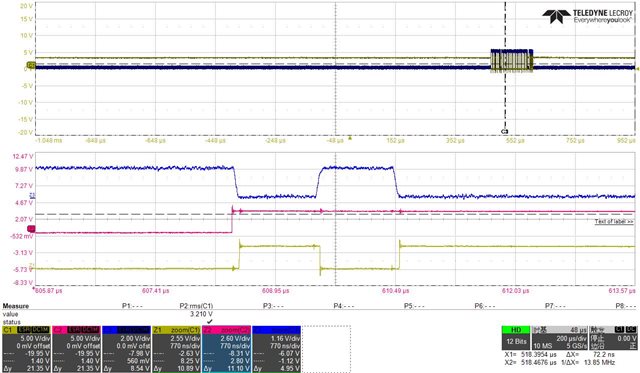
 用示波器看图上三个点的波形,点的颜色对应波形的颜色。

 从图上可以看出,中间红色波形(MCU发出端),后面已经没有报文了,但是蓝色波形(总线上)还有一个高电平。黄色波形(cpu接收端)有了一个低电平。

仔细看的话,可能看出来红色波形后面有两个小小凸起,不知道是因为这两个小凸起导致蓝色总线上电平变化,还是总线上电平的变化,导致红色端波形有凸起?

忽略掉总线,只看MCU和CPU端,MCU已经没有高低电平变化了,但是CPU端还是有个低电平,这看起来不太对。

求解~谢谢!

  • The bumps on the red line are noise, and harmless.

    This might be an ACK bit. Please check the Tx signal of the CPU (and of any other CAN devices on the bus).

  • Yulong,

    Thanks for posting this to E2E. As Clemens said, the bumps on the TRX signal are harmless, and probably just the result of the parasitic capacitance and inductance inherent to the CAN bus as the signal transitions from high to low. 

    As for the extra bit, Clemens is also probably correct here, it looks like the ACK bit at the end of a correctly received message. Is this at the end of a CAN frame?

    Regards,

    Eric Hackett