A related question is a question created from another question. When the related question is created, it will be automatically linked to the original question.
If you have a related question, please click the "Ask a related question" button in the top right corner. The newly created question will be automatically linked to this question.
Can the left and right Vref be connected to 1.8V as a switch? I'm worried that there will be a problem with the internal MOS bias voltage. Thanks a lot.
When using the PCA9306 as a switch, you connect the EN pin directly to the (lower) supply voltage. In that case, VREF1/VREF2 are not used (and the 200 kΩ resistor is not necessary); you can let them float, connect them to the same voltage on both sides, or use them as a third data channel.
I compared spec's 8.1.5 It seems that the main difference is that switch mode EN can be directly pulled out to control In translation mode, both Vref2 and EN2 need to have 200K pull up.
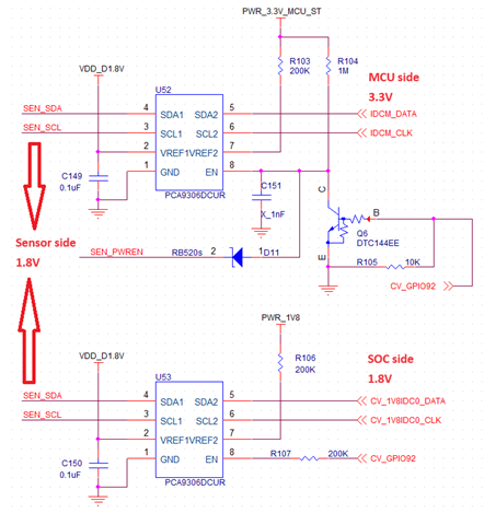
Our current design requirements are as follows Please help me confirm the line below. 1. MCU 3.3V, SoC 1.8V, Sensor 1.8V 2. U52 is translation mode, U53 is switch mode 3. Only U52 or U53 turn on at the same time (Use CV_GPIO92 to control U53, and use BJT to reversely control U52) 4. If SEN_PWREN is pulled low, U52 and U53 will turn off.