A related question is a question created from another question. When the related question is created, it will be automatically linked to the original question.
If you have a related question, please click the "Ask a related question" button in the top right corner. The newly created question will be automatically linked to this question.
Both of our experts for these devices are on vacation for US holiday, and won't return until after the new year. Please allow us some time to address this question.
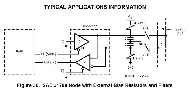
So while J1708 applications do ground the DI pin - this device can still be used in non J1708 applications in which you would send data through the DI pin.
So figure 5 would represent a situation that isn't relevant to J1708 - but just standard RS-485.
In J1708 the low to high propagation delay is the time to disable the driver and for the external network to charge. In normal conditions this is 11ns (typical) and up to 60ns (max) for the device to disable while outputting a low value - however its external network has a much smaller RC time constant; so a lot of the delay is actually due to external system.
For the high to low propagation delay it is the enable time to low + discharge time of external capacitors. The enable time to a low value is typically 30ns but up to 60ns(max) - however the J1708 external network once again has a much larger capacitance so this spec could slow down a bit in actual system.
So in conclusion:
1. This is still an RS-485 compliant device. Figure 5 is more relevant to classical RS-485 than to J1708 and can be ignored for J1708 designs.
2. The "prop delay" as seen by system is actually going to be from the enable to low time (TPZL) + external discharge time for the high to low propagation delay (TPHL) and the disable from low (TPLZ) + external charge time for the effective low to high propagation delay (TPLH) in J1708 applications.