


Part Number: DS125DF1610EVM
Other Parts Discussed in Thread: DS125DF1610
Dear Lucas,
We don’t have an access to the programming guide. Would you be kind enough sharing it with us.
Assuming the PRBS needs the clock generated by the CDR to be turned on, then we can’t use the DS125Df1610EVB in our application as planned.
Is there a possibility that the PRBS generator will be turned on independently of the clock generated by the CDR (clock REF for instance)?
Please note that the application suggested in:
DS125DF1610EVM: how to use DS125DF1610 as a Bert - Interface forum - Interface - TI E2E support forums Is misleading, since based on your information above, my understanding is that the data source to the receiver can’t be the data generated by the PRBS generator located on the same DS125DF1610EVB. I would like to suggest that this should be mention emphatically in the suggested application.
Furthermore, please note that the block diagram of the DS125DF1610 in the data sheet is differ from the block diagram diagram in the EVB GUI (the internal PRBS generator is connected differently)
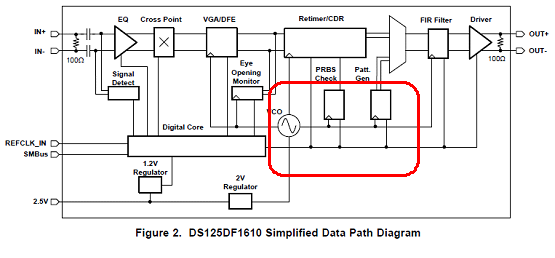

Obviously the differences are misleading! in the data sheet the PRBS Generator clock is independent from the CDR recovered clock and in the GUI it appears that the PRBS gen is connected the incoming data (?).
I'm repeating again what is/was our plan:
Thanks
Motti
