This thread has been locked.

If you have a related question, please click the "Ask a related question" button in the top right corner. The newly created question will be automatically linked to this question.

AM26C32: Split Termination for RS-422 - Cutoff Frequency

Part Number: AM26C32
Other Parts Discussed in Thread: AM26C31, TIDA-01401, TIDA-060027, TIDA-00731, , THVD1400

Hello Community,

We are designing an end-use case using an AM26C31x pair for our data transmission of upto 4Mhz maximum & 500kHz typical. I want to confirm the following:

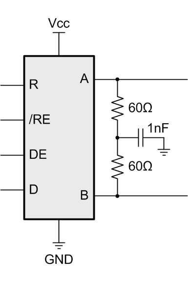
  1. Having UTP CAT6 cable, do we benefit from Split Termination instead of single resistor termination?
  2. Using AC Termination - can we effectively limit the EMI by slowing the edges? Added advantage is lower power
  3. Do we need to add RC-based LP filters on the R/D side?
  4. We have selected SM712 for EDS, EFT & Surge protection on A/B side for both C31 & C32
  5. Any other robust EMC guideline that is available from TI for AM26C3x devices or RS422 in general, none is published on the product page
  6. Any suggestions on the use of Ferrite beads on the A/B side?

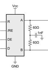
Split Termination is suitable/beneficial what frequency shall be selected for cut-off at/above/below the data rate? Does it matter?

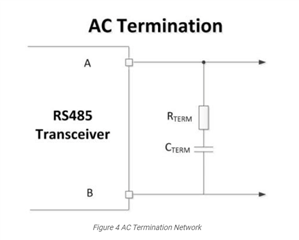
Will AC Termination be a better choice if we can slow down the edges as our speed requirements are lower ~4Mhz at most.

Thanks & regards

  • 1. Split termination is more important for CAN, where the bus is not driven during the recessive state. RS-422 drivers like the AM26C31 drive both states on the bus, so it will have less of an effect. However, the TIDA-01401 reference design optionally uses it.

    2. Yes, AC termination filters out high-frequency noise (and high-frequency signals, which cannot be used). For details, see section 5 of AN-903 A Comparison of Differential Termination Techniques.

    3. If the traces between the transceiver and the MCU are short, you do not need additional components. For longer traces, a source termination resistor is usually enough. But if you expect that high-frequency noise can be coupled in, adding a low-pass filter would be possible.

    5. RS-422 and RS-485 are mostly identical. See, for example, Protecting RS-485 Interfaces Against Lethal Electrical Transients, TIDA-00731, and TIDA-060027.

    6. In practice, R-C filters are used because they are cheaper (and typical 10 Ω resistors do not affect the drive strength too much). Sometimes, for added common-mode noise reduction, common-mode chokes are used.

  • Hello Clemens,

    1. We find Split Termination easier for our use case - what limits the selection of the Capacitor (ie RC constant)? The common mode cutoff should not affect the differential signal's integrity, is this a right assumption in real use cases? The TIDA-01401 uses a 470pF cap that has a cutoff frequency in range of ~80MHz, can we bring down this cutoff frequency to as low as 1-2MHz? Any issues doing this? The lower this frequency the better noise filtering? Is this a flawed concept?

    2. There are two different suggestion in the application note for Resistors matching 0.1% & 1% - can you guide how much of an influence will a 1% over 0.1% have as the cost delta is significant between these two choices.

    3. Shall we use Ferrite beads directly on the A & B to filter out the 100Mhz & beyond noise at both ends of driver & the receiver? Any recommendations for Ferrite bead use case? 

    4. Do we need to add external biasing resistors for AM26C32 devices? The DS mentions it has inbuilt biasing circuit. However some readings contradicted this, kindly guide.

    Additional contextual information:

    We have less than 100 feet maximum of cable length in the system, with most common legnth being 12-15ft, the maximum data rate shall be 4Mhz for the clock signal & all other channels with data packets shall be less than 1Mbps. There are no stubs on the route, mostly point to point.

    Your guidance shall be highly insighful for our decision making.

  • 1. The capacitor selection is explained in AN-903. Split termination slows down all signals; to pass through high-frequency differential signals, you would need a common-mode choke.

    2. Mismatched resistors would convert common-mode noise into differential noise (and thus affect the signal). You can compute how much a certain amount of noise would reduce the noise margin at the receiver. AC termination would not have this problem.

    3. This is possible. Ferrite beads are more expensive than R-C filters, but have lower DC resistance. In general, the latter is not really important, but it might matter for very long cables with a large total resistance.

    4. In general, the AM26C32 needs external fail-safe resistors. But with AC termination, an idle bus will not be shorted through the termination, so if that is your only concern, then you do not need fail-safe resistors. (But you might care about a shorted bus.)

  • Hello Clemens,

    Thanks for your feedback.

    The capacitor selection is explained in AN-903.

    There is no mention of Split Termination in AN-903, is it the same document - here

    Split termination slows down all signals;

    There is this SSZTB40 where the author says:

    "Typical concerns I have heard with this termination technique include, “Will this filter my CAN bus signals?” and “Do I need to place the corner frequency above my data rate?” The simple answer to both questions is no. Since the capacitor does not place a direct current (DC) load on the differential bus signal – it only filters the alternating current (AC) signal and the common-mode signal – and the differential signal is what determines the bus state, you do not need to set the corner frequency of the filter above the data rate."

    Hence my doubts about the capacitor selection in Split type termination.

  • Sorry; I was confusing AC and split termination.

    For split termination with matched resistors, the capacitor value indeed does not matter.

  • Hi Neet,

    Clemens is correct on his points here - but please don't hesitate if you have any other questions. 

    Best,

    Parker Dodson

  • Hello Park & Clemens,

    We have stuided the ANs & have created following design decisions for our use case.Can you kindly review & share your valueable feedback on the attached schematic?

    We have added Split termination with 0.5% tolerance resisitors of 50Ohm each with 1.8nF bypass capacitor to form a LPF for Common mode noise.

    Kindly ignore the R40 to R56 (they were 10Ohm series resistors)

    RC based filter on the MCU side to further reduce the transient spikes.

    Can we also use the same split termination for RS485 using THVD1400?

    Looking forward for your valuable feedback.

  • Looks OK, but C50…C53 should be behind the resistors.

    Yes, you can treat RS-422 and RS-485 termination resistors in the same way.