This thread has been locked.

If you have a related question, please click the "Ask a related question" button in the top right corner. The newly created question will be automatically linked to this question.

THVD1429: Modbus Data packet errors: Some data will be lost/missed

Part Number: THVD1429
Other Parts Discussed in Thread: THVD1400, THVD1420, THVD2410

Hi,

We are using THVD1429DR RS485 IC with CC3220MODSF12MOBR.

We are reading 30 parameters (1 Packet) from slave Device. Frequency: 1 parameter per sec. Baud Rate 9600 bps.

We are noticing some issue while reading the data from the slave devices. Mean, some Parameters are some times not receiving, but most of the time we missing parameters, we cant guess which parameter to be missed. In missed parameter we are printing the reasons. reason will be Slave not responding, Extra size,etc.

But same slave device modbus connected with PC using USB to Modbus Converter all the 30 parameters received without fail, all the time.

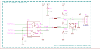
I have replaced 220 Ohm ferrite bead with 0 Ohm Resistor and also we tried with populating 523 Ohm Resistor on R12, R13. But printing same issue.

Please find the schematic FYI. Kindly advice to resolve this issue.
  • Please show an oscilloscope trace of the A/B signals and their difference for a failing packet.

  • Hi Clemens,

    Thank you for the response.

    We are not having Oscilloscope now and it may take some time to get it. We will get soon and trace out.

    Meanwhile, without Oscilloscope, could you please suggest us any other trials to find/resolve the issue.

    Thanks and regards,

    Naveen K

  • There is nothing obviously wrong with the schematic. Seeing the actual signals is necessary to be able to debug this.

  • Hi Naveen,

    As Clemens mentioned - please attach the scope signal of the differential signal so we can better tell what the signal quality looks like. 

    That being said - why do you have an external TVS diode - this device has integrated protection and this will make the communication nodes very capacitive which could cause potential issues (will be easier to tell with scope shots).

    Please let me know when you can get the scope captures. 

    Best,

    Parker Dodson

  • Hi Clemens and Parker,

    Sure, We will get the Oscilloscope soon and share you the captured signal waves.

    Meanwhile, could you please advise for our below mentioned query.

    1. we are also using the part THVD1420DR and in the datasheet recommended to use TVS diode. If the multiple parallel diodes causing issue means we will un-populate for the THVD1429DR boards.

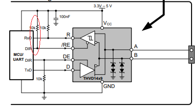
    2. As shown in the schematic, we are not using Pull-up resistors in the RO-pin, Pull-up is mandatory to use or in which situation we can use?

    3. In THVD1429DR datasheet, /RE pin has pul-up resistor and connected to separate MCU pin. In our Schematic, We have shorted the /RE-DE pin, Pulled-Down with 10KOhm and connected to MCU pin. Which one will be efficient? How/Where we can differentiate whether we can use as per our schematic or as per the datasheet?

    4. We need to proceed for the next Production and we are holding till resolve this issue. We need to know whether any changes required in the Design or Firmware.

    5. Comparatively THVD1429DR and THVD1420DR, having huge price difference. Except Internal ESD Protection Diodes, Any other major Difference/ advantages between these parts? In which condition/Application we can consider which Part? Please advise it will values for us in all prospective.

    Thanks and regards,

    Naveen K

  • 1. We do not know if this actually is a problem. If the capacitance is too high, the signal edges are too slow (this would be visible in the scope capture).

    2. You need a pull-up on RO if you MCU's RXD pin needs a valid signal even when the receiver is disabled. This is usually the case.

    3. The DE and /RE pins have opposite polarity to allow them to be connected together. You need separate control signals only if you want to enable or disable both the driver and receiver at the same time.

    5. The THVD1429 would allow a slightly higher data rate (which you are not using). If you want to use external protection components, you could just as well use the THVD1420 instead. (But for slow signals, a slow transceiver like the THVD1400 reduces EMI.)

  • Hi Naveen,

    Thanks - I look forward to seeing the scope captures. 

    1. I am not sure if the capacitance is the issue - as Clemens said though this will be visible on the scope captures if this is the issue

    2. If the pull-up is mandatory or not depends on the controller and higher level data protocol you are using as it is extremely common for it to be necessary due to controller possibly throwing errors or missing data if it is not included. 

    3. Shorting /RE and DE together and controlling it as one pin where a low turns on receiver and high turns on driver is completely fine and generally much more common than having separate lines. The only time you would need separate lines is if you need the driver and receiver either enabled at the same time or disabled at the same time - and generally speaking for half duplex devices most use cases won't have the driver/receiver active at the same time. The use case for both TX and RX being disabled at the same time is that the IC will consume significantly less power when both TX/RX are shutdown - in some applications there may be a lot of idle time for the RS485 so reducing power usage may be wanted/warranted. If you don't need the added power savings by putting the device into a completely disabled state then shorting the two pins as you have done is fine. 

    4. It will be easier to determine that after I see the scope shots - if there is a hardware problem with the transceivers it will show on the scope signals - if not the problem exists at the controller either from a hardware issue or a firmware one - but at this time I can't say with full confidence the exact issue. 

    5. The main price difference is due to the integrated surge protection on the THVD1429 - as we physically integrate a TVS diode into the package that is not present on the THVD1420. The THVD1429 is a bit higher speed - but you don't need that in your application. Realistically the THVD1400 would be a better option as we typically try to suggest that designers choose the slowest part possible that still meets the needs of the application. I generally don't suggest parallel TVS diodes (external and integrated in this case) for protection - usually I'd suggest an external diode + the THVD2410 for an application like yours because of four reasons:

    5.1. external clamping in the system is usually more robust than any integrated solution we offer and its generally a little easier to design with

    5.2. The THVD24x0 family has +/-70V fault tolerant inputs - which allows for simpler protection schemes than standard RS-485 applications. 

    5.3. You can get away with a less robust external diode - because it won't have to clamp as low and therefore may not need as high of a power rating (but higher working voltages).  Depending on fault condition you are protecting against you may not even need the external protection device

    5.4. The THVD2410 is similar in price to the THVD1429 - but generally the 2410 is a little easier to build into applications with a high level of robustness that is wanted. The THVD1429 doesn't have very high fault ratings - so even during clamping there is a possibility it clamps too high for itself which could lead to damage - and generally we don't see as many issues with the THVD2410 + external diode. Since you already have an external diode I would consider looking at the THVD2410 - it should be pin to pin with the THVD1429 if you are using the SOIC package because I generally have seen that you get better results from those pairings. The THVD1429 is a good choice if you have smaller surges expected and there is a size concern on the communication nodes. 

    I understanding making a switch would most likely not work at this moment directly, but it is a very good part that works very well in these types of protection schemes as shown without as many of the negative tradeoffs that the designer has to make with the THVD1429 and is also one of our more popular devices. I think it may be worth at least a look. 

    Please, when you are able to get them, I'd greatly appreciate the scope shots as that will be the next best step in determining if there is a hardware problem that needs to be rectified at all. 

    Best,

    Parker Dodson