Dear support team,
My customer is evaluating with DP83TG720.
DP83TG720 Media Converter Evaluation Module
MSP430F5528 plays a role in it,
According to the design (Figure 6-3. Schematic : MCU), I have a few questions for you.
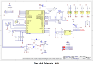
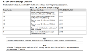
1. MCU's pin 5/6/7/8 connected to DIP switch, what's the function for? Do they have to keep it or can change to pull-high/pull-down resistor?
2. MCU's pin 18~25 connected to LED, do they have to keep it?
3. MCU's pin 50/52 connected to micro USB connector, is this for debugging?
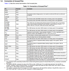
4. If the MCU's pin isnt' used, the user should connect it to the ground?
Thanks!