


Part Number: TCAN1462-Q1
I have a question regarding the placement of a common mode choke; why would the common mode choke be placed between the termination resistors and the transceiver, instead of being between the termination resistors and the transceiver (indicated with red arrow)? The image is taken from the TI SLLA271 application note (https://www.ti.com/lit/an/slla271/slla271.pdf?ts=1704355254549)
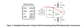
I think it is preferable to have a high impedance common mode path to board GND for high frequency EMI currents.
This CM choke for example, has a 3000 ohm impedance at 10 MHz: https://www.we-online.com/components/products/datasheet/744235510.pdf, while the common mode impedance of the termination network is about 30 ohm to GND (if we ignore the capacitor). So, moving the CM choke to the cable side increases the impedance for high frequencies significantly. Thanks in advance!

