This thread has been locked.

If you have a related question, please click the "Ask a related question" button in the top right corner. The newly created question will be automatically linked to this question.

DS90UB954-Q1: DS90UB954----DS90UB933 LINK ON, but no signal output

Part Number: DS90UB954-Q1

Dear TI:

1、问题描述:

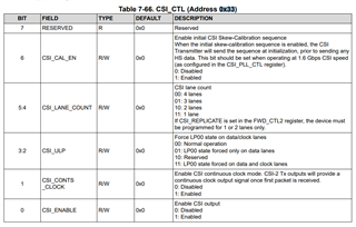
    为适配带串化器为UB933的摄像头(解串器为UB954),按照附件初始化配置在soc端初始化954-933寄存器,初始化结束后,发现ub933-UB954能够LINK上,但查看0X4D寄存器,寄存器值始终为0x03--即无信号输入给      到 ub954; 另外ub954 0x73-0x76 寄存器值保持不变,摄像头无法出图。

2、硬件环境:

    连接方式:soc主控-----DS90UB954----DS90UB933 -------senosr

3、期待结果:

   954-933寄存器信号能够正常传输;

4、疑问点:

  场帧内同步和外同步有啥区别?什么时候该用内同步什么时候该用外同步?

  设置0x5b,设置了i2c_pass_through ,是否Link上,是否可以通过查看0X5b寄存器是否为slave i2c address判断?

5、附件:

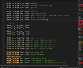
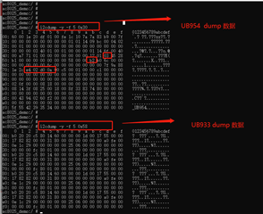
附件1:UB954-933在soc的初始化配置、系统端dump数据:


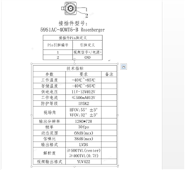
附件2:适配的摄像头参数(带串化器UB933)
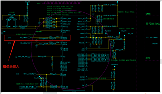
附件3:摄像头连接原理图

Best Regards

期待能够得到解答,非常感谢!

  • Hello, 

    0x4D is expected to have a value of 0x03 when the devices are locked. Is the goal of this test changing the camera resolution? 

    Internal frame sync uses the SerDes devices to generate the FrameSync signal to the cameras. External FrameSync assumes an outside component will supply the signal at a GPIO pin on the deserializer. This signal will then be sent over the back channel to the serializer. These can be selected on a system preference. 

    The SER address in register 0x5B will reflect the serializer on the RX port that was selected to read from in 0x4C. This register value will remain the same with I2C pass through enabled and disabled. I2C passthrough enabled will allow I2C transactions to be sent to the serializer. 

  • Hi

       I am using register 0X4D to determine whether UB954 has a signal. 

       Is there anything wrong with the configuration of my ub954-ub933 mentioned above? The  system schematic is attached in the problem. Now I suspect that the camera cannot display normally because of the configuration problem. Where can I check. 

     Thanks for help

  • Hello, 

    Monitoring register 0x4D on the deserializer is primarily used to determine if there is lock between the serializer and deserializer. For lock between the serializer and deserializer to occur, the deserializer will be locked to the forward channel sent from the serializer. For lock to be established, there does not need to be video data sent from the serializer to deserializer.

    The register 0x35[0] will help monitor if the CSI transmitter is operating as expected. CSI port pass denotes valid data is available on at least one port.

    Additionally, register 0x73-0x76 show the line length and line count of the video data that is being received by the deserializer. These values correlate to the most recent video line and length. 

    Checking the register dumps, it appears that the devices are operating correctly. 

    I see in the schematic, only the first two CSI lanes are being used but four lane forwarding is selected. Would you be able to first update UB954 0x33 from 0x03 to 0x23? 

    camera cannot display normally because of the configuration problem. Where can I check. 

    If the problem persists, I recommend testing with pattern generator from the deserializer and serializer. Has this testing been done? 

    Best,

    Zoe