This thread has been locked.

If you have a related question, please click the "Ask a related question" button in the top right corner. The newly created question will be automatically linked to this question.

LMH1208: LMH1208 & LMH1219

Part Number: LMH1208
Other Parts Discussed in Thread: LMH1219, LMH1297, LMH1297EVM

hello,

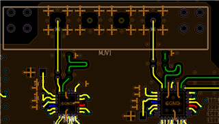
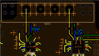
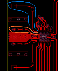
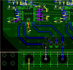
I need help with the 75ohm lines. The datasheet tells me " The trace routing for SDI_OUT1+ and
SDI_OUT1– should be as symmetrical as possible, with approximately equal lengths and equal loading."

It doesn't tell me the tolerance... how much does it matter? 

My video path is LMH1219 to 2 LMH1208.

I'm trying to figure out what to do, should I use serpentine technique? to match the total length? 

(I'm on 3G SDI).

  • There is no single tolerance value. Having different lengths or loading makes the analog characteristics of the signal worse, which increases the risk of transmission errors.

    Make them as equal as possible. If your software supports serpentine routing, use it.

  • Hi Aviad,

    Yes, try to match the total length.

    Best,

    Nick

  • so better this:

    than this:

    as long as the total length of the P and N line are equal, I'm fine?

    And does the distance between the IC'S Pin to the 4.7uF capacitor are important? I mean is it ok that one capacitor length is longer than the other one, but the Total length is matched.

  • Hi Aviad,

    Thanks for your question. It is a good idea to match the P and N of SDI_OUT if possible, but not doing so will not have a significant effect on return loss and other signal integrity specifications.

    Our own EVM design does not match the LMH1297 (pin compatible with LMH1208) SDIOUT P and N as shown below:

    In the LMH1297 EVM which is designed by TI, the orange(SDIOUT-) and blue(SDIOUT+) circled traces are not trace length matched 

    In reference to your question about the length of the IC pin to the capacitor -- In the interest of the device's differential output signal integrity, it is best that the P and N traces are exactly the same. However, in reality this is often not possible and there can be differences between the two traces.

    The LMH1297EVM layout can be a reference for your design. Do you have access to it?

    Best Regards,

    Nick

  • Hey, Thanks a lot for the answer.

    I have the PDF file of the EVM without layout of him, are you sharing the layout somewhere?

    I think that I mislead you, I asked not of the differential pairs, but for the 75ohm outputs/Inputs (in general of those devices). At the positive pin there is a capacitor (4.7uF) after the pins, and then there is the connectors. At the negative pin, after the pin there is capacitor(4.7uF) and after him there is a resistor(75ohm).

    I wanted to ask about the length of the pin IC's to those capacitors, I do understand that it is affecting on the return loss and other signal integrity specifications, but how much is the trade off between those two, I mean obviously you never could match it perfectly but there is no number for tolerancing? this x length affect in y dmg.. ?

    Thanks again,

    Aviad

  • Hi Aviad,

    I sent you a friend request and can share the layout files with you via direct message once you accept for your reference. 

    I think I understand your question now. I believe the issue is if a tolerance were to be established there would be too many variables and possible orientations to account for. For example, a 100 mil difference in the P and N side could increase insertion loss by a small percentage x, could also decrease return loss by a small percentage y, could change VOD by z, etc. while if you had a 100 mil difference in the P and N side, with the capacitors at different points on the traces, and used a different PCB material those variables would change the loss characteristics to a different degree. Basically, it's like a one shoe doesn't fit all situation and each design has it's own tolerances. If you wanted to get a good idea of the tolerances for your own design, certain PCB simulators like Ansys electronics are good.

    Best Regards,

    Nick P.