This thread has been locked.

If you have a related question, please click the "Ask a related question" button in the top right corner. The newly created question will be automatically linked to this question.

THVD1429: PC side no data signal

Part Number: THVD1429
Other Parts Discussed in Thread: SN65HVD72EVM

Hi Team,

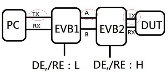
the current test is to use Ti SN65HVD7x EVB *2 and change THVD1429 sample ( only switch DE/ RE, determine the direction), transmit command.

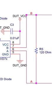
the DUT (STB) on the schematic diagram is connected to the Debug port, the schematic diagram is shown below, the A and B signals of EVM only measure the 3.3v voltage level, no DIFF signal.

may we know is there connection correct? and the DE/RE signals setting correct? thanks.

the terminal resistance of EVM is 120ohm, see the figure below:

  • Do you mean the SN65HVD72EVM?

    Please check the voltage of the VCC, DE, and D pins at the chip itself.

  • Hi Tommy,

    In your current setup - it is set where the DUT can communicate back with the PC. 

    EVB1 is set to receive mode - that means the "D" pin on EVB1 is a don't care value - because only "R" pin is active in this configuration. 

    EVB2 is set to transmit mode - this means that the signal into "D" on EVB2 will be converted to a differential signal on A/B pins of EVB2. 

    So for the test setup to work as shown:

    1) DUT sends data onto "D" pin of EVB2

    2) EVB2 coverts "D" pin datastream to differential signal and outputs that on A/B pins of EVB2

    3) EVB1 converts differential input signal on A/B pins into single ended signal and outputs signal on "R" pin of EVB1

    4) PC should be able to read signal on "R" pin. 

    If you are following these steps and still not seeing data there are a few things to check

    1. Verify the VCC level. 

    2. Verify the "L" value on EVB1 on the DE and /RE pins is between 0V to 0.8V. 

    3. Verify the "H" value on EVB2 on the DE and /RE pins is between 2V and VCC. 

    4. Verify that the DUT is sending data onto "D" pin for EVB2 - a scope capture would be helpful as it can show the Signal quality as well to see if there is a potential issue there

    5. Measure the voltage at A and B and capture scope shots if there is any signal. 

    6. Try to capture a scope shot of the "R" pin - if any data is coming out at all. 

    Can you please try verify and capture the following scope shots if possible so I can look at bit deeper in to the issue. 

    Also I have 2 clarification questions that could also help in my investigation.

    1. Does the problem only occur when you switch the IC to the THVD1429? 

    2. If yes to the above question - can you please post a picture of the top markings of the THVD1429 that you are using so I can trace it back into our system. 

    Best,

    Parker Dodson