This thread has been locked.

If you have a related question, please click the "Ask a related question" button in the top right corner. The newly created question will be automatically linked to this question.

SN65HVD12: more than 5 devices on the bus fails

Other Parts Discussed in Thread: SN65HVD12

Dear All,

I have connected RS485 IC (SN65HVD12) to LPC2387FBD100K microcontroller the attached is image for the references,

The Communication is by using UART.

I am facing the problem of the Multi slave communication, where as I successfully observed 5 slaves are working fine.

More than 5 slave are not working, If I connect 6th slave to device then its not working means still 5 slave working but 6th slave not working.

My aim is to connect more than 10 slave communication.

Please assist, if any other docume nt required please let me know.

  • Hi Sagar,

    So I have a few questions for you to help isolate the issue in your application. 

    1. What is the network topology that you are using - (daisy chain, spine + junction box, start, ring, etc....) ? 

    2. How long is the bus at its maximum length? 

    3. What data rate are you running at? 

    Please let me know because I do think part of the problem is most likely with the above questions. 

    Next I do want to point out some concerns I have with the schematic - I am assuming that all nodes are designed the same way - if that is not the case please let me know though. 

    1) So this setup is not RS-485 compliant. In RS-485 there are multiple requirements - but 2 of the largest ones are proper termination and maximum bus loading; this setup looks like it will violate both. 

    1a) So in RS-485 both terminal nodes (start and end node) should be terminated between A and B with a 120 Ohm resistor and the bus's characteristic impedance should also be apprx. 120 Ohms. This is to improve signal quality along the bus by mitigating reflections (regardless if your data-rate is slow there will be potential chances for reflections at signal transition periods because there will be a lot of higher frequency signal content at that point). Now while RS-485 doesn't specify a specific network topology - because of the termination requirement the best choice is Daisy chain, followed by spine with junction boxes - every other topology is highly discouraged.  Bad SI can result in communication failure. 

    1b) All RS-485 devices are designed to be able to drive 32 Unit Loads in parallel - since this device is 1/8th unit load its theoretical maximum is 256 communication nodes per bus. However - that assumes that there is no other loading on the bus - which you have very large biasing resistors. 32 Unit loads in parallel can also be shown as its approximate impedance value - which is 375 ohms. Since schematic shows biasing resistors at 1k - if you have 5 in parallels; the resistors alone violate the 375 Ohm minimum loading. Having 1 pair of 1k biasing resistors is okay if you want to increase the noise margin of the receiver a bit - but at every node 1k is not going to work. What I would suggest is 2 things and you could do either. The first is that if you want your final biasing value to be 1k - then if you have 10 nodes each resistor should be 10k 

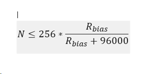
    Essentially the following equation will give a max node count when adding biasing resistors to every node. 

    The following equation assumes that if there are N nodes in system then there are N pairs of biasing resistors. Also the input impedance of a 1/8th unit load device is assumed to be 96k - which is where the 96000 value comes from. 

    So your max node count when adding external biasing resistors is 256 * R_bias/(R_bias + 96000). So for an Rbias of 1k the max node count should be between 2 and 3 nodes before you enter a place where you are overloading the driver. 

    To simplify the BOM cost however - you can just use 1 pair of 1k resistor and not have to add them to every node. In general we suggest that biasing resistors are only added to one node - but if it is easier from your side to not do that than the Rbias value will need to increase. 


    Please let me know on the three top questions - but ultimately I think you are overloading the device which could be causing the issues. 

    Best,

    Parker Dodson

  • Hi Mr. Parker,

    Thanks for your prompt reply,

    The Answers are
    1. What is the network topology that you are using - (daisy chain, spine + junction box, start, ring, etc....) ?  

         Answer :  daisy chain topology by using Half Duplex mode.

    2. How long is the bus at its maximum length? 

       Answer : Near about 500 Mtr. With Max slave support with same topology.

    3. What data rate are you running at?  

      Answer : From Lower 9600 to 115200 Buad Rate should support.

    Also I have connected 240 ohm Termination resistor in between the A and B by Pulling up And down to 1K,

    Waiting for the answer, should I manage the resistor in such a way that it will work for the same,

    Also how to? 

    Can you suggest correct values of the same?

  • Hi Sagar,

    So its good that you are using a daisy chain network topology as that is the preferred network topology for RS-485. No issues there. 

    Do you have every node terminated on the bus? 

    Does every node have a pull-up on A to VCC that is 1000 ohms? 

    Does every node have a pull-down on B to GND that is 1000 ohms?

    If you have answered yes to any of the above questions then there is a problem with the setup.

    1. Only the first and last node should be terminated. This should be 120 Ohms each - 240 and you most likely will be getting significant reflections. The cabling should also be ~120 ohms. At 500m  you cannot deviate from standard whatsoever 

    2. If you are adding Pull-ups and Pull-downs on every node the max number of nodes is bounded by the following equation:

    Your Rbias value is 1000 - the max nodes is less than 3 when you do that. 

    So if you have 10 nodes your 1k resistor needs to go to 10k and that should be fine. 

    Or you only have 1 pair of 1k resistors (1 on the "A" line to VCC and 1 on the "B" line to GND") - do not put them on every node. 

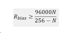
    The max value of Rbias, if they are added to every node, can be found by rearranging the above equation:

    Where N is the number of nodes. 

    You technically do not need them at all - but if you are going to keep them they need to be increased. 

    As I said in the first reply - the bus is most likely overloaded because of the pull-up/pull-down resistors. 

    Best,

    Parker Dodson