This thread has been locked.

If you have a related question, please click the "Ask a related question" button in the top right corner. The newly created question will be automatically linked to this question.

DP83822IF: Basic initialization of the PHY

Part Number: DP83822IF
Other Parts Discussed in Thread: ALLIGATOR

I'm using an FPGA to write to the PHY registers as I do with other PHYs.

I send 32 ONEs as a preamble followed by:

SOF 0b01

OPCODE 0b01 (for write)

PHY ADDR 0b00001 (per datasheet 8.5.3)

REG ADDR 0x00 (BMCR)

I set bits 8 & 13 = 1 and bit 12 = 0

Then same SOF/OPCODE/PHYADDR but REG ADDR 0x0A with bit 14 = 1 (for FX enable)

I'm not being successful with this.

Is there something I'm missing?

  • Hello,

    Can you atleast establish that you are able to access the PHY in the first place to establish a baseline? Please try reading Reg 0x2 and 0x3. These are read-only values whose only value should be reflected in the datasheet. This will confirm the PHY is alive.

    Next, regarding your write, can you read back to ensure that those changes kept?

    Another thing to keep mindful of is the turnaround bit between the register and the written value; there should be another '10' in between.

    Sincerely,

    Gerome

  • I'll have to write something in Verilog to read those registers.  I put in the turnaround bits but forgot to show it.

  • Hi Craig,

    I will await your results.

    Sincerely,

    Gerome

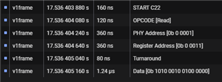
  • I successfully read register 0x3 and I get the default values per datasheet:

    I decided to solder on some wires to MDIO and MDC.  Then uses my SALEAE analyzer.

    We use another PHY and write all kinds of settings successfully.  Soldered on some wires there as well.

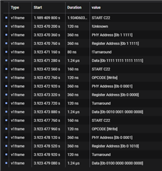
    When I look at the analyzer for the TI PHY (in question), The write commands and addressing looks correct.

    The mess at the top appears to be the preamble - SALEAE MDIO decoder must have trouble with that.  The other PHY exhibits same.

    So I'm not sure why the TI PHY will not initialize - I have to be missing something.

  • Hi Craig,

    This is good that you are able to access the PHY to some degree. So you are trying to initialize the PHY to disable auto-negotiation and force 100mbps full duplex, in addition to enabling 100base-fx. You are claiming that you are unsuccessful, but what is going on when you write this? Are you able to read back the respective changes you wrote? Are you having functional issues? 

    Sincerely,

    Gerome

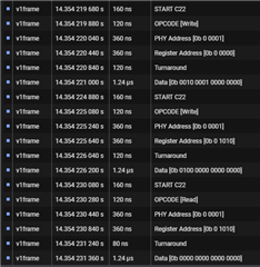
  • Yes, that is what I'm trying to accomplish.  When I read 0xA immediately after I try writing bit 14 (FX Enable), it appears that it was not set:

    It's not taking my settings and the PHY is not functioning for me.  For example, neither the RX nor TX clock is operating.  I can see these clocks in Chipscope (Xilinx ISE),

  • Hi Craig,

    I will need to check on this. Is your write command on Reg 0x0 not working? Trying to isolate if this is due to Reg 0xA being finicky or the write command itself.

    Sincerely,

    Gerome

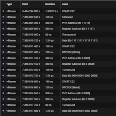
  • Here is the write to 0x0 and then a read from 0x0:

    A little different I'm seeing bit 8 get set but bit 13 is not.

  • FYI,

    Not sure if you know Dajon McGill.  I've contacted him for technical support but I realize now that you are also TI.  Thought you were just another member.  In the event you are contacted about a suspiciously familiar case/problem you'll know that's me. 

  • Hi Craig,

    Thanks for the info. If Dajon is handling this, I will defer to him.

    It does seem weird that only partially the write is going through. This would lead me to believe there is a setup/hold time issue during the write command that is causing this issue. Is it possible to scope this out via oscilloscope as well as logic analyzer?

    Sincerely,

    Gerome

  • I filled out detailed checklist with Dajon so it will be a while until I hear back.  I can put a scope on both MDIO and MDC.  What should I look for?

  • Hi Craig,

    I would be checking for setup/hold time during the write sequence, especially during the payload of the SMI to see if it is in spec with our datasheet.

    Sincerely,

    Gerome

  • Hi Gerome,

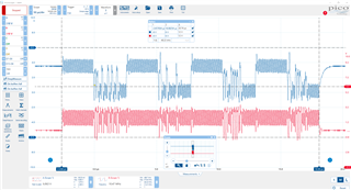
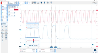
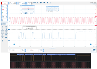
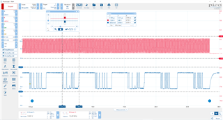
    Here is a screenshot of my scope I'm writing to 0x0 then reading it back then writing 0xA then reading it back:

    MDIO in blue and MDC in red - does MDC look right to you?

  • Hi Craig,

    I am concerned with the noise that is on the line in addition to the sharpness of the waveform. It almost seems like its being undersampled so its difficult to provide an effective analysis. Assuming that each "burst" is one write command, is it possible to zoom in? Perhaps that will take care of the undersampling and provide clearer insight.

    Also, if the noise is truly present on the line, it is advised to remedy that.

    I see in the schematics there is a DP83826 also on schematic. Is that also seeing issues as well as DP83822?

    Sincerely,

    Gerome

  • Gerome,

    So far in this development project I've only brought one of the Broadcom parts to life.  Here is the waveform:

    Similar "noise"?  The Broadcom part does successfully initialize.  This is what I'm writing to it:

  • To your point though there seems to be noise to address.  I'll attempt to improve my resolution/sampling.

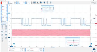
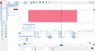
  • I had the little alligator clip ground tied to something that was NOT ground.  Here is a much-improved waveform: 

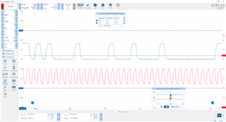
    I zoomed in on the first burst on MDIO:

  • Hi Craig,

    This helps a lot! Now that we have a clearer image, and also since you can dissect the timing diagram better, can you confirm that the datasheet specs below are being met for the entirety of the write command? Specifically, I am curious about T2 and T3. In addition, what is the frequency you are addressing this PHY at?

    Sincerely,

    Gerome

  • In this example... T2+T3 = 79ns.  T2 about 40 ns.  This is typical.

    MDC frequency is 12.5 MHz

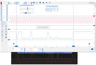
    Also, these spikes look suspicious to me.  They only appear on the reads.  First I write to 0x0, then read 0x0.  Then write 0xA, then read it.

  • Gerome,

    I just noticed that T1 is about 40ns in all cases.  This exceeds the spec of T1<=10ns.

    Thanks,

    Craig

  • I get nearly identical behavior using a slower 5 MHz clock:

  • Hi Craig,

    This is very strange behavior. Do you know when in the read process this is occurring? As the line is bi-directional, this may be indicative of contention issues between the MCU and PHY.

    In addition, is this issue reproducible on this single board? Or on other instances of these boards?

    Sincerely,

    Gerome

  • Gerome,

    I'll zoom in on the read's and determine which bits have a problem.  Is that what you mean?

    I've got the other two TI PHYs on the board but they are different parts.  However, I have a second board (something to test against).  I'll need to tack down some leads on MDIO and MDC to scope it.

    I'll work on these items this AM.

    Thanks,

    Craig


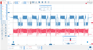
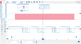
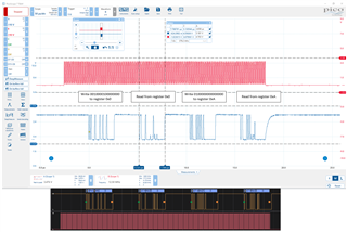
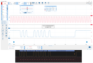
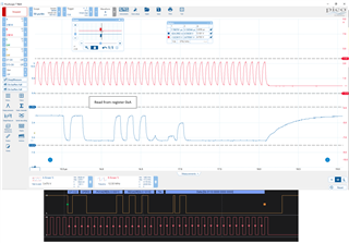
  • I found similar behavior with the PHY on what we can call Board 2.  This problem is reproducible.  I made up some screenshots that pull together the scope and analyzer results.  Hopefully this will offer some additional insight.

  • Hi Craig,

    When this blips occur, when in the SMI communication is this happening? Eg is this happening during the register, turnaround, PHY address, or payload portion?

    Sincerely,

    Gerome

  • Mostly I see blips in the payload region.  Although I see a small blip either at the end of the register address or start of turnaround but the analyzer fails to recognize it.

  • Hi Craig,

    If this is in the payload region, this is when the PHY is supposed to be taking control of the line and shooting out its register value. However, the behavior is indicative that something else may be interfering with this operation; whether it be the SoC failing to release the line, or something else. In theory, this line is supposed to be open-drain, so the PHY's job is to only hold the line down when there is a '0' and then release when there is a '1'.

    It could be plausible that the write command is going through, but the interference on read is disguising this '1' as a '0' and vise versa to the SoC upon readback.

    I would want to check that the SoC is not interfering with this operation.

    Sincerely,

    Gerome

  • It's entirely possible that the FPGA is interfering with the READ operation.  I will investigate that.

    Given that, maybe the WRITE commands are going thru ok but I've got some interference on readback as you say.

    Here's another question.  Assuming I solve the readback problem, are the settings I'm writing sufficient to enable FX comms?  I expected that once the PHY is configured I would get one of the LEDs solid on the fiber transceiver.

  • Hi Craig,

    For FX application, the only bit required to flip is Reg 0xA[14]. 

    However, I would like to ask why not strap the PHY initially into FX mode if this is the intended use case. This would remove the dependency on having to reconfigure after powerup. To enable via strap, the COL pin (29) would need to be set into modes 2 or 3 via resistor divider network.

    Sincerely,

    Gerome

  • Hi Gerome,

    I've come to the conclusion that it was my Verilog that was the problem.  I unwittingly had the MDIO line set to output only versus inout for bidirectional.

    I'm now able to readback my writes with some confidence.  What I see now when I readback register 0x0 includes bit 11 high for IEEE Power Down.  Which I did not set.  Could this explain why I'm seeing no signs that the PHY is active.  I'm using two indications to determine whether the PHY is active.  1) RX and TX clocks moving as seen in Chipscope (should also see RX data) and 2) LED lit at transceiver.

  • Hi Craig,

    The EVM is reading this bit as a '0', but also once this pin dynamically changes to have a low state, this bit is a '1'. I also wanted to check if this pin is accidently being set low via pin. This would require a quick multimeter check. I did notice that there is no PU populated for this line; only a PD, so the SoC would need to drive the line to ensure this is high.

    If you were to manually set this bit as '0', does the readback hold?

    What does the SMI waveform look like in the scope?

    When you mean you are using two indications for the PHY being up or not, are you not seeing RX_CLK toggling?

    Sincerely,

    Gerome

  • At the moment I only have the SoC (FPGA) to read and write these registers.

    I write and read twice from 0x0

    write 0x0 / read 0x0 / write 0x0 / read 0x0 / write 0xA / read 0xA

    Correct, I do not see any activity on RX_CLK or TX_CLK via Chipscope (following initialization).

  • in first two writes I set bits 3 & 8 high - in both cases I readback bit 11 as high as well.  Which was not intended.

    I see power_down pin in being pulled down.  I'll drive it high and report back.

  • That did it!  The power_down pin is being driven high.  Problem solved.  The PHY has come alive.  All along this was the culprit.  Was obfuscated by the read problem.