This thread has been locked.

If you have a related question, please click the "Ask a related question" button in the top right corner. The newly created question will be automatically linked to this question.

TCAN1144-Q1: CANLGND unreliable detection

Part Number: TCAN1144-Q1
Other Parts Discussed in Thread: TCAN1145EVM

Hello,

I have been testing the TCAN1144 and prototyping implementing it into some existing hardware.

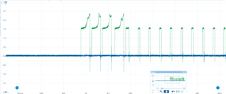
The bus fault detection functionality it being tested via a custom spidev program which polls the INTCANBUS register every 1 second and reports the status of the faults.

It has successfully been able to detect all the faults its says it can with the exception of CANLGND which it detects sporadically. Also every now and again it falsely detects half termination.

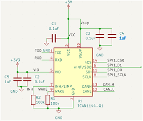
The chip is configured like so, with INH and wake being pulled to GND as they are unused.

However, the power, spi ,and can connections all break off from a breakout board and are soldered to pads of a pre-existing PCB so the setup is less than savory.

The can bus that the transceiver is being tested on is rather short in length so this shouldn't be the issue.

Previously the chip was tested with a TCAN1145EVM where the TX, RX & SPI wires were fed to the EVM from the pre-existing PCB and it was found to work reasonably reliably. But with the new setup, this is not the case.

Any Ideas on what sort of difference/conditions could cause the chip to be behaving unreliably when detecting this error?

Kind regards,

Max

  • Small update,

    The transceiver consistently detects the CANLGND fault condition at the time it occurs (as long as traffic is being sent over the bus not from itself at the time of the occurrence) , but after the INT_CANBUS register has been cleared and the fault is still present it fails to reset the register.

  • Hi Max,

    The bus fault detection circuit for this device monitors the output current of the CAN pins to determine if there is an anomaly with the CAN bus. The transceiver expects a symmetrical and consistent current through both CANH and CANL when driving a dominant state on the CAN bus. If an different amount of current is detected through CANH and CANL, the device interprets this as a short on one of the CAN lines (CANH to Vcc, CANH to GND, CANL to Vcc, CANL to GND). It will use the amount of current that is being measured from both driver pins to determine which of these faults to report. For example if little-to-no current is output from CANL while a larger than typical current is output from CANH, the device will interpret this condition as a CANL short to GND. 

    Note that the transceiver is only capable of detecting bus faults when it is actively driving a dominant state on the bus. This is because only a small amount of current is used to bias the recessive state (logic 1 and idle state) which is not enough to reliably measure the bus fault status. The transceiver takes a measurement of the bus fault circuit whenever the CAN driver has been in the dominant state for a sufficient amount of time and transitions to the recessive state. This typical happens when the transceiver is transmitting at 500kbps or slower. If the transceiver detects a fault condition for four consecutive dominant-to-recessive transitions, it will set the corresponding bit in the INT_CANBUS register. Once the MCU has recognized that this flag has been set, it will need to clear it manually by writing a 1 to the corresponding bit field of this register. 

    The thresholds for the bus fault detection current thresholds are set internally to the device and are valued such that they will be exceeded if conditions outside of a typical CAN system are met. This can include excess series resistance on the CAN bus, excess leakage on one of the CAN signal lines, ringing or other complex AC behavior from passives like CMCs, bus capacitors, and parasitics, and several other bus characteristics. Because you describe the CAN connections from the board to the transceiver are less than ideal, I suspect that this may be playing a part in the CANL to GND detection. 

    For this feature, I recommend using the information from the bus fault detection in conjunction with other information from the system. For instance, if there are no increases in CAN errors while transmitting or receiving in the system, the presence of non-ideal conditions on the CAN bus as reported by the transceiver may be largely irrelevant as the conditions are not significant enough to impact signal reliability. However if detected in conjunction with an increase of CAN errors or a bus-off state, the bus fault condition reported by the transceiver can be helpful diagnostic data for a technician that is trying to rule out other potential issues to narrow it down to a cable harness or similar hardware failure. 

    Let me know if this information is clear and if you have any more questions. 

    Regards, 
    Eric Schott 

  • Thanks for the reply Eric,

    Just a little confused about the following

    "For example if little-to-no current is output from CANL while a larger than typical current is output from CANH, the device will interpret this condition as a CANL short to GND. " I would have thought that CANL would be the wire with a larger than typical current as it is being shorted to GND and the transceiver is trying to drive it to ~1.5 volts.

    Also do you have any ideas on why the transceiver might be able to detect the fault upon the moment of it occurring  but not after the fact? A larger amount of initial current when the fault occurs or something like that?

    Kind regards,

    Max

  • Upon examining https://www.ti.com/lit/ta/ssztbo8/ssztbo8.pdf . What you said now makes sense, I had a different view of how I thought the transceiver was driving the bus.

  • Hi Max,

    Yes, as you saw from this document the CANL pin is driving to ground potential, so a short to ground on this signal pin would result in almost no current flowing from the pin. 

    The sporadic detection of some faults is generally caused by the length of dominant time presented in the data stream. When a longer string of dominant (logic 0) bits are driven on the bus, the transceiver is able to get a more accurate reading of the bus state as the system has more time to settle to a steady state. Shorter dominant strings may cause false negatives or false positives due to the ringing of the system as it changes from a recessive to dominant state. This could explain the sporadic detection behavior you are seeing in your testing .

    Regards, 
    Eric Schott 

  • That answers my questions, thanks very much Eric.

  • Sorry for opening this thread again but it's so related to the information above I thought it might be best. Upon some further testing based on your information, it is indeed the length of the dominant strings of bits which determines whether or not the error is detected & sporadic half termination.

    In my setup, at least 3 dominant bits must be driven in a row for the voltage (and hence the current as the impedance should be roughly constant) to reach a high enough level where detection is possible when CANLGND is present. (I imagine this is due to stray capacitance)

    Going off this quote from the datasheet(https://www.ti.com/lit/ds/symlink/tcan1144-q1.pdf) of

    "Detection takes place and is recorded if the fault is present during four dominant to recessive transitions with each dominant bit being ≥ 2 μs"

    I need exactly four of these spikes you see in the above waveform for the fault to be detected. Those spikes correspond to a frame from id 000, of 0F-FF-FF-FF-FF-FF-FF-FF. This seems distinctly related to the above quote.

    The bitrate is 250kbps and hence the width of an individual bit is 4uS, meeting the 2uS requirement.

    The bit stuffing bits appear to be being interpreted correctly as dominant bits, but my guess is they don't meet the requirement of being "dominant" for the purpose of the above quote.

    Would you say this is an accurate representation of whats going on? And is there some data on the maximum amount of current needed to trigger the condition?

    Do you have any suggestions/tips about what can be done to keep the setup more reliable, besides decreasing stray capacitance?

    Currently the plan going forward is probably just going to be to send some diagnostic can frames of all zeroes to check for the CANLGND condition if it appears once (it does sporadically appear as sometimes frames will conform to the above).

    Thanks very much for your help,

    Max

  • Hi Max,

    Thanks for the update on your testing. This all sounds consistent with the expected behavior of the device. Sending "fault detection frames" like this one with a payload of all dominant bits is a common recommendation from us as it satisfies all of the requirements of the transceivers fault detection feature and gives the most time possible for the bus to settle between stuff bits without modifying the CAN data rate. 

    The transceiver has a set minimum dominant time that it will use for the fault detection feature, throwing out any measurements from dominant drive states shorter than this time. However as you've seen, the minimum time that it may actually take for the system to settle to an appropriate state may be longer than this. The thresholds for current and voltage in the fault detection circuit are unfortunately a bit optimistic in this regard, so they are more likely to recognize no fault when the dominant time is too short as many real CAN systems with parasitics accounted for will look good for longer than 2µs. One of the primary contributors of this is actually the common mode choke as this improves the symmetry of the signal even in the faulted state. 

    Do you have any suggestions/tips about what can be done to keep the setup more reliable

    This is tricky because in order to improve the response time of the signal to a fault in order to detect it more reliably, we may be making the system less stable in In the nominal case. For example CMC may keep the signal stable for longer than 2µs during a bus fault condition, and without it we may see the fault before 2µs and be able to detect this condition more reliably. However, without the CMC we are allowing  more common mode noise in the system when  no fault is present and could lead to degraded performance vs the same system with the CMC. We may also have an example where communication works under some fault condition due to the marginal improvements made by the system that also cause a false-negative reading of the fault detection circuit. In this case we would be choosing between a system that can transmit (albeit with a few more possible can errors) during a fault case but may not recognize the fault and a system that can  consistently recognize the fault but would not be able to communicate during it. If combined with the possibility of sending fault detection frames when CAN errors are detected, the first case seems preferable to me. 

    Let me know what you end up moving forward with as I'm always interested to see how cases like this where the system settle time exceeds the device minimum time are handled. 

    Regards, 
    Eric Schott