This thread has been locked.

If you have a related question, please click the "Ask a related question" button in the top right corner. The newly created question will be automatically linked to this question.

DS90UB954-Q1: to DS90UB953-Q1 MIPI-CSI-2 to split data out of existing FPD-link III

Part Number: DS90UB954-Q1
Other Parts Discussed in Thread: DS90UB960-Q1, DS90UB953-Q1

Hello

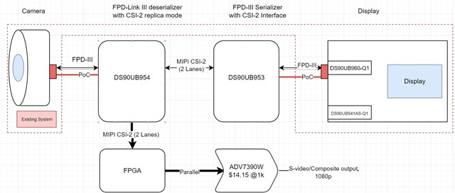
Similar to previous posts, I need to split/break into an FPD-III link so that camera data can be displayed live and also recorded. I've tried to highlight the existing system in red.

From what I can gather, it should be possible to take the FPD-III from the camera and split it into two identical MIPI CSI-2 outputs, one of these feeds will be used by an FPGA for processing, the other will be reserialized and passed to the original system display. The display uses deserializer DS90UB960-Q1, but I can't currently get any information on what serializer is being used in the camera, as it's a potted assembly.

The video format is 1080p @30Hz.


So my questions are:
1 - Without knowing what device is serializing the camera data, is it possible to say if this system will work? I know in a lot of other threads there's been quite specific lists of compatible parts. The DS90UB960-Q1 states that it is compatible with the DS90UB953-Q1, so I think we're okay on that side of the link.
2 - Will the secondary control data (I2C), bridge the MIPI CSI-2 link?
3 - If the MIPI CSI-2 data to the FPGA has the control data embedded in it, is this going to cause issues for processing? From what I can gather, the bidirectional control data is proprietary to TI, so I'm not sure how it will be handled.

Thanks

Dan

  • Hi Dan,

    Thank you for your question. It doesn't look like the image of your system has attached properly, could you try to post it again? In general duplicating and sending the same identical CSI outputs to different portions of a system is possible. The DS90UB960 for example has two CSI output ports as well as a replicate feature, which will result in the second port outputting a replicated copy of the first port. From what you've described, it sounds like the replicate feature is a potential solution. 

    1. In general replicating the CSI data to output to two locations is possible. However, the exact configuration and programming necessary can vary depending on which serializer and deserializer are being paired together. If you can provide some more details on which devices you plan to use, I can verify compatibility. The DS90UB953 and the DS90UB960 are compatible so if the camera is using a DS90UB953 then the DS90UB960 would be a good choice to receive and duplicate the camera data.
    2. Are you asking if I2C transactions can be output with the CSI data on the deserializer CSI output port? Every FPD-Link device does have dedicated SDA and SCL pins for I2C communication and I2C transactions can be sent between the serializer and deserializer via the FPD-Link channel.
    3. The FPD-Link channel does not modify any of the incoming CSI data. However, the devices still expect to receive CSI data. What control data is expected to be embedded in the CSI data? Are you referring to control data specific to the CSI protocol such as the CSI data packet header and footer?

    Regards,
    Darrah

    1. Hi Darrah
      Thank you for getting back to me, I'm not sure if the image is completely missing or you're referring to the part I left off deliberately as I didn't think it was necessarily relevant. Either way I think the new attachment should be visible.

    Responses to your answers below:

    1 - So the devices will be Camera  >> UB954 >> UB953 >> UB960. And the original system was Camera >> UB960. The UB954 and UB953 will be on a separate PCB to the camera and Display. Power to the camera is via the Display FAKRA connector, they're installed a number of meters apart.

    2 - I'm assuming that in the original system I2C communications were sent across the bi-directional FPD link, between camera and display, and I want to preserve (or replicate) this if possible. Would I need to connect the I2C pins of the  DS90UB953 and DS90UB954 or would the data be carried across the MIPI CSI link? Sorry if I'm asking the same question again, I just want to make sure what I'm trying to do is clear.

    3 - I was referring to the I2C communications, I think an answer to question 2 will make this clearer.

    I have one further question:

    4 - If this link is viable, what delay is deserializing and reserializing likely to cause between camera and display? I imagine the answer will be along the lines of "it depends", in which case what would be the main contributing factors to this delay and how would we best remedy them?

    Many Thanks

    Dan

  • Hi Dan,

    Thanks for the image, this helps clear up what your system is doing. So the additional 954 is the device generating the two streams of replicated data not the 960. Is the goal to modify the system in a way that neither the camera or the display boards' hardware or software need to be modified? The reason I'm asking is that the 960 on the display can be used to replicate as well, so if the board can be modified additional devices may not be needed. However, if it is easier to add additional devices than it would be to rework the entire system, the 954 and 953 addition will work as well.

    To answer your questions:

    1. This line up should be compatible. If the camera is able to lock onto and function properly with the 960 in the original system, then the camera should be compatible with a 954 as well. If you have the original system available you may be able to determine which serializer is being used by the camera via the device's registers. There are ID registers that can be read to determine the device, for example see registers 0xF0 - 0xF5 on the 953. 

    2. The bi-directional FPD-Link channel does send I2C communication between the serializer and deserializer boards, which would be how the original system functioned. The I2C communication can only travel on the FPD-Link channel or the I2C bus directly, the MIPI CSI output port will only output the CSI data. In order to maintain end to end I2C communication from the camera to the display the I2C pins of the 954 and 953 will need to be connected.

    3. The MIPI CSI data output by the 954 and received by the FPGA will only contain the MIPI CSI data. There will not be any I2C communication in the 954 output. In order to send I2C communication to the FPGA, the FPGA will need to be connected to the I2C bus lines.

    4. Comparing the additional 954 and 953 to the original system, any extra delay would come from the MIPI CSI data transfer from the 954 to the 953 and the second FPD-Link channel transmission. The MIPI CSI data transfer from the 954 to the 953 speed will mainly depend on the speed that the 954 is programmed to transmit the data. The speed of the transmitter is programmable for 400Mbps, 800Mbps, 1.5Gbps, or 1.6Gbps. For details on programming the transmitter frequency see section 7.4.21 of the 954 datasheet. The delay of the FPD-Link channel is mostly driven by the line buffer of the deserializer, other delays such as propagation delays of the signal and the act of serializing are nominal by comparison. There is not much that can be done to minimize this delay, but the delay can be estimated as 2x the line time. This E2E has an example.