Problem phenomenon:
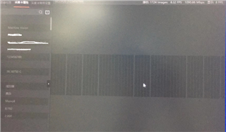
Symptom: In Full mode (clock frequency 85Mhz), the display appears vertical stripes (the content displayed is the content captured by the camera).
Waveform capture: DS90UB928QSQX is found when problems occur, channels X0, X1, X3 high-speed undecoded data out, data packet loss, only X2 decoded data out;
Temporary solution: the problem does not recur after replacing the IC with 421/422;
Requirements: How to locate and resolve the packet loss problem?
Connection mode:
DS90UB927QSQX end is connected to the camera cameralink interface
DS90UB928QSQX end connection (cameralink interface) Capture card(PC)
Transmission content:
DS90UB927QSQX serial transmission of 4 LVDS signals and 1 CLCK signal (clock frequency 85Mhz),
The DS90UB928QSQX unstrings the data and sends it to the acquisition card.
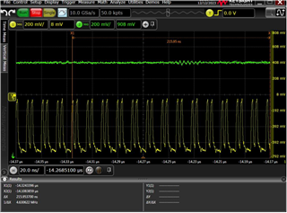
In case of vertical stripes (yellow line is 927 input, green line is 928 output)