This thread has been locked.

If you have a related question, please click the "Ask a related question" button in the top right corner. The newly created question will be automatically linked to this question.

DS90UB953-Q1EVM: DS90UB953-Q1

Part Number: DS90UB953-Q1EVM

Hi,

From lots of the discussion in the forum, the parallel resistor on POC circuit's inductor is mainly to not make the impedance so high when the frequency is close to the SRF of the inductor.
But I don't quite understand why it is important for the design.  It seems once the impedance is over 1k, this path will be as an open one for the LVDS signal.
What is the real benefit to make the impendence smooth near the SRF?

Thanks
Don

  • Don,

    The goal is to provide high impedance across the entire frequency band that the FPD channel operates across since the scrambled signal doesn't just contain one frequency component. Without these parallel resistances, the impedance will be high in a narrow band around the inductor SRF, but will be low at frequencies further away from that point. Adding the resistor spreads out the impedance over a wider bandwidth (lowers the Q factor)

    Best Regards,

    Casey 

  • Hi Casey,

    Thanks, but I think the parallel resistor cannot make the impedance higher on the band out of the SRF. It just decreases the peak impedance near the SRF.
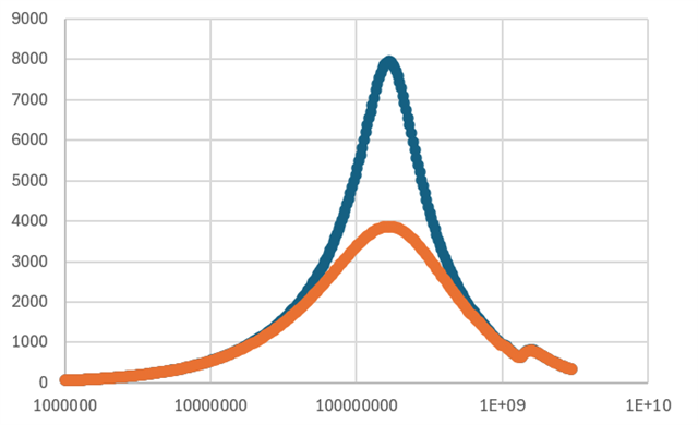
    I try to plot it below. The blue one is the inductor's impedance and the orange one is with a 4k resistor in parallel.
    So I don't feel it spreads out the impedance and helps any. Please correct me if I have any misunderstanding.

    Don

  • Don,

    You won't be able to see the desired effect by looking at just one component in isolation. You will see the effect when multiple inductive components are placed in series as you typically have with a PoC network. For example the one in the 953 datasheet includes a 10uH inductor and multiple FBs in series. Here is a snapshot of the low frequency area showing with/without the 4k ohm parallel resistor. In this specific case you can see improvement of the impedance around 50-200MHz (x axis is MHz, y axis is impedance). Other networks will show differences depending on the component selection

    Each network we qualify has been tuned via the specific inductor/FB selection and the parallel resistances to ensure we have good coverage of impedance across the entire working frequency bandwidth of the link 

    Best Regards,
    Casey 

  • Hi Casey,

    Thank you.
    Do you have a raw data file for me to check how your figure is calculated? I am still struggling to make such plot.
    From my understanding, as those parts(FB、each inductor+parallel resistor pair) are in series, so their impedance are added together.
    It looks the final impedance of the whole circuit will be like the shape of my figure occurs on different SRF and all added together.

    Like the following one. And if the blue trace are added together and comparing to the orange one(also added togather), the blue trace is still always higher than the orange one at any frequency.

    So it's  hard for me to image adding a parallel resistor will increase the impedance on some frequency as what your plot shows.
    Please correct me if I have any misunderstanding.

    Don

  • Don,

    I am simulating s-parameters for the PoC network from the 953 datasheet using ADS. The simulation is using the s-parameter models from all the FBs, inductor, and PCB trace segments of an example design:

    Then I am extracting an plotting mag(Z(1,1))

    Best Regards,

    Casey 

  • Hi Casey,

    Got it. Thanks for the information.

    Don