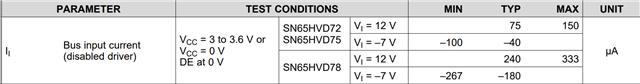
This thread has been locked.

If you have a related question, please click the "Ask a related question" button in the top right corner. The newly created question will be automatically linked to this question.

SN65HVD72: Violating maximum number of devices on the RS485 bus?

Part Number: SN65HVD72

Hello TI forum -

I have an application that incorporates 500 SN65HVD72 devices on a RS485 bus. The bus consists of 1000' 24AWG 120ohm twisted-pair cable with drops every 2'. Data rate is 115.2kbps. Terminations on both ends are 120ohm.

At any given time, only 1 device will be transmitting and only 30 devices will be receiving. All other drops will have their receivers and transmitters disabled. Since the SN65HVD72 transceivers are 3/20UL devices, only 213 should be connected to the bus. However, I'm wondering if this specification applies to 213 active receivers and our application therefore doesn't violate this spec and is safe to do?

We presently have this system running in our lab. The signals look excellent with no data errors. Here is an example of the signal from the furthest drop on the bus:
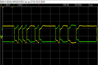
Thank you

  • Hi George,

    The standard refers to receivers on the bus - inactive or active. In general there isn't much difference between the loading current between inactive and active states for most RS-485 devices. I.e. the differential receivers are never truly high impedance because there is an attenuation network before the high impedance receiver that is the primary driver that sets the input impedance on the bus (the Unit loading number). So adding 500 devices to a RS-485 with this device is inherently risky because you are stressing out the driver. 

    This is shown in the bus input current - which is where the unit load number is derived. The test conditions are VCC = 3V to 3.6V and VCC = 0V. 

    With that being said - it may not be impossible to communicate - as it seems you have set it up in your lab and it works okay - but essentially it is no longer RS-485 compliant which can have some risk.

    Best case scenario you most likely see increased power dissipation that could lead to premature part failure.

    Worst case scenario - the drivers current limit is triggered and wear and tear on part increases while communication is impossible - so failure in application and premature part failure. 

    So this is not something we'd advise. 

    The way to do something like this is usually to use a repeater. We do have a reference on how to create them (https://www.ti.com/lit/ug/tidu590/tidu590.pdf?ts=1706299251014&ref_url=https%253A%252F%252Fwww.google.com%252F) - the specific design is for 100kbps - but the architecture wouldn't change much for faster designs - but values and chosen device may need to change. This design uses a isolated transceiver as the main 2 reasons to use a repeater is if you need a longer bus at the selected data-rate  or there are large ground potential shifts between nodes on bus  which isolators can help tackle both of those issues. However another less common use is to increase node density on the bus - and since you have > 2x allowable nodes we'd suggest two repeaters on the line - but since you are less than 4000' at your data rate and it doesn't seem like you need more common mode range than the 72 provides (which helps with ground potential differences) you may not need to use an isolated transceiver and can use standard ones.

    However that begs the question why you chose the SN65HVD72 - I ask because most of our modern devices are 1/8UL so you'd only need one repeater. The trade-off of adding the repeater is bus complexity increases and throughput on the bus will also decrease because the repeater will have a much longer propagation delay than if it wasn't there). 

    Please let me know on why you chose the SN65HVD72 as we may have a better option that can help simplify the overall system design.

    Best,

    Parker Dodson

  • To reduce the stress on the drivers, you could use AC termination. But this would slow down signal edges.

  • AC Termination does not give designers a free pass to overload bus - risk is not fully mitigated and designer assumes responsibility of system failure if bus is overloaded. 

  • Hello Parker - thank you for your fast response.

    Actually repeaters are part of the original design. These 500 drops are divided into 100 drop segments, with repeaters between each segment. Very similar design to your app note, except we're using the SN65HVD72 instead of the isolated transceiver. We chose the SN65HVD72 for a number of reasons - availability being a major concern.

    We notice that when the bus is driven low, signal quality looks good. However when the transceiver is allowed to float high there appears to be a long time constant to the signal's edge. I'm assuming this may be a result of the cable capacitance. We've tried various power termination resistor combinations - although not the  590/133/590 network as shown in your app note. We also noticed considerable reduction in pk/pk signal amplitude with all terminations schemes that we tried.

    We will continue to troubleshoot this issue today and hopefully make some progress. As far as the termination is concerned, would you suggest 590/133/590 terminations at both ends of each bus segment or only on one end with a single 120 ohm resistor located at the other end?

    thank you,

    George

  • Hello Parker -

    An update - we resolved our issue with the repeaters (wrong time constant calculation) and now all 500 drops are reading well with repeaters located after every 100 drops. Thank you for your time and fast response to my query!

    George

  • Hi George,

    I am glad that you were able to fix the issues you were seeing! I have no issue with the repeater setup as you have stated either. 

    Please let me know if you have any other questions and I will see what I can do!

    Best,

    Parker Dodson