


Part Number: DS90UH949-Q1
Other Parts Discussed in Thread: DS90UB949-Q1, DS90UH948-Q1
Hello,
We are designing an HDMI to FPDLINK converter board to drive a display that includes DS90UH948-Q1. We are using DS90UB949-Q1. We examined the layout example of the datasheet to connect the Rosenberger HSD connector. You show that right-angle HSD connector in the example. There is a space between signal pins and mounting pins(ground). You drew the signals through the space between mounting pins and signal pins. But we will use a straight HSD connector.
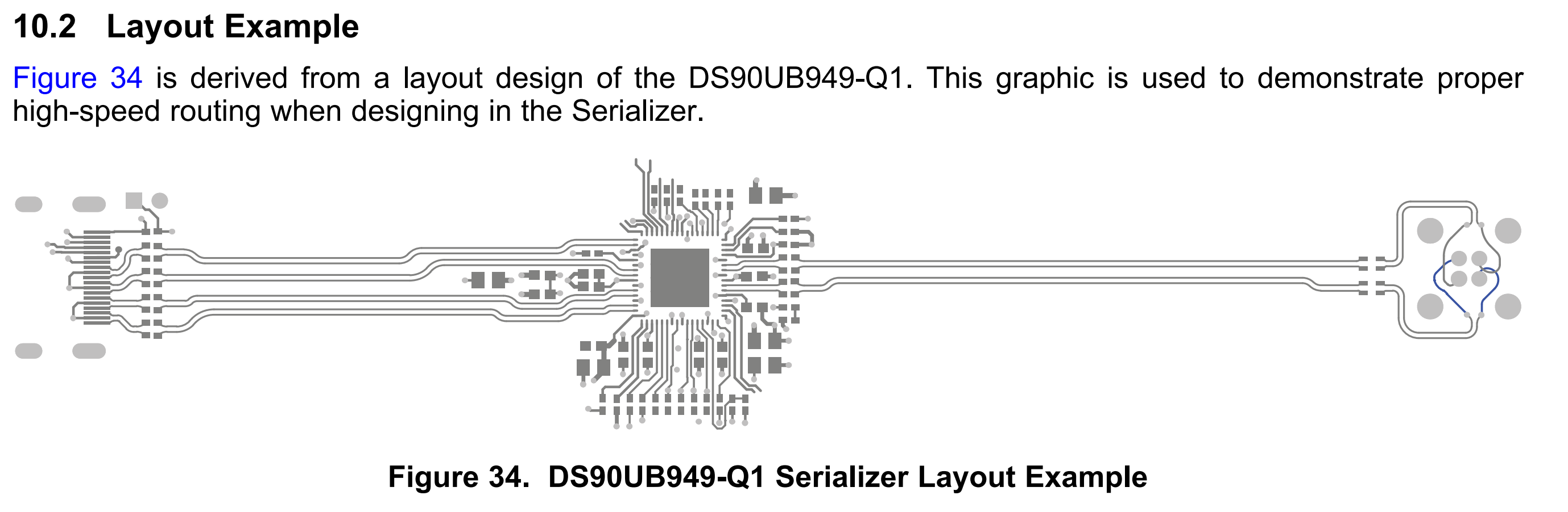
Your example with right angle HSD connector:
Your example with right angle HSD connector layout:
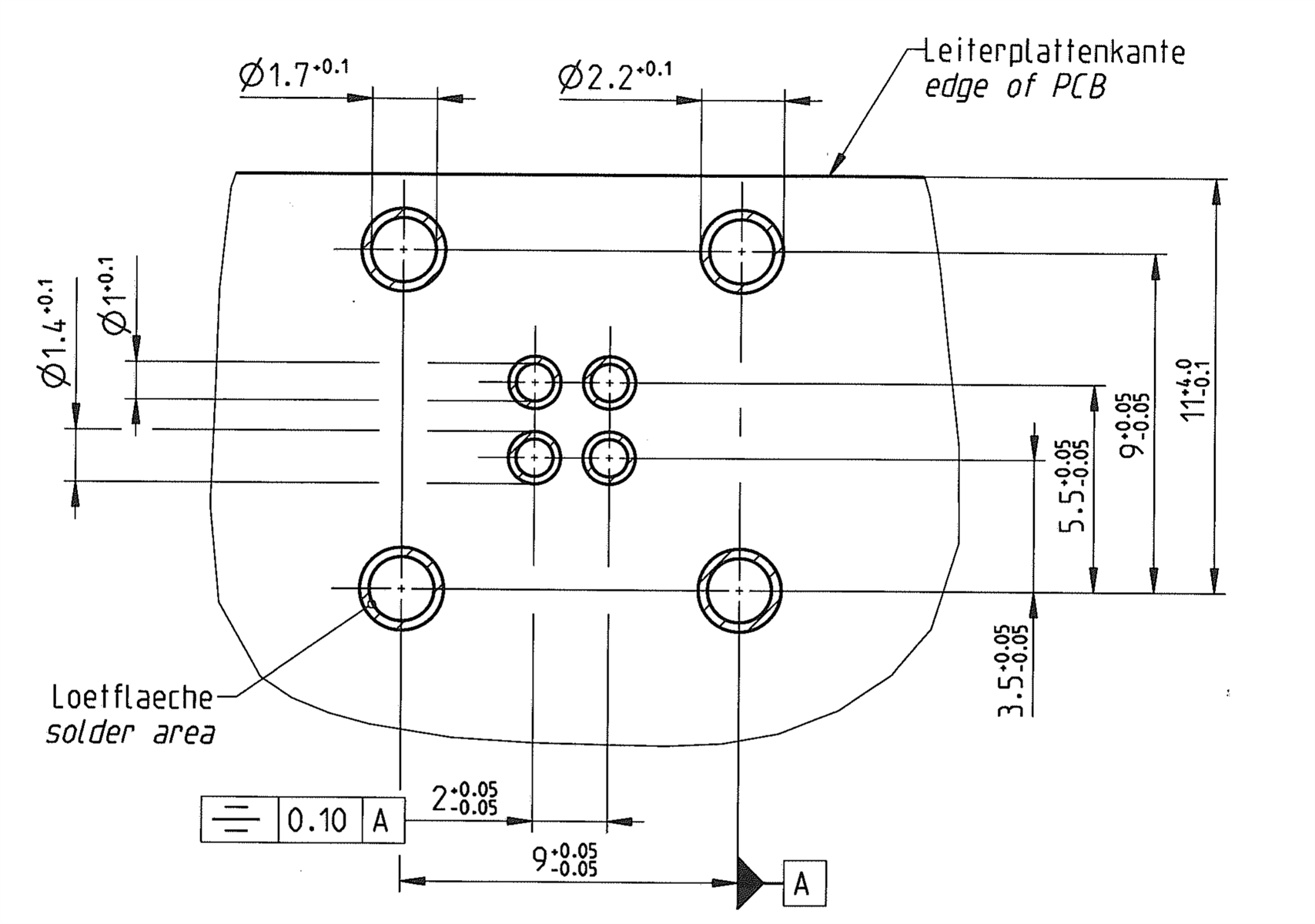
Your datasheet example with right angle HSD connector:
Our application with straight HSD connector:
Our application with straight HSD connector layout:
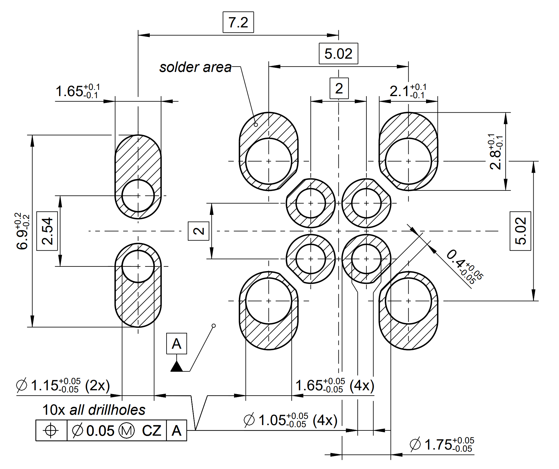
Our application with straight HSD connector:
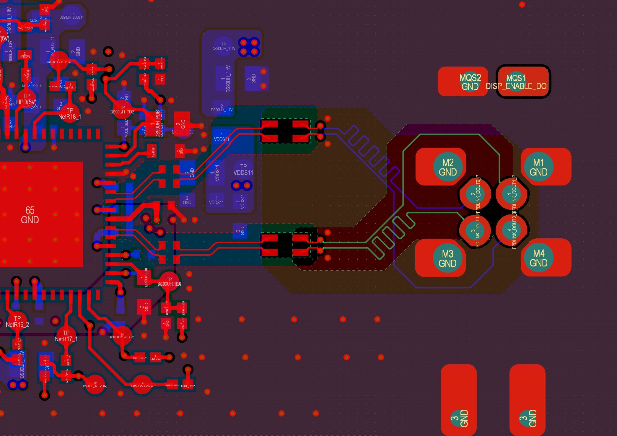
The space of straight HSD between mounting pins and signal pins is too low. We can not use this space. We drew different layouts to connect straight HSD connector as you see above picture. Is our application layout proper to connect a straight HSD connector? Or How can we route the tracks?
