This thread has been locked.

If you have a related question, please click the "Ask a related question" button in the top right corner. The newly created question will be automatically linked to this question.

TCA9548A: Does TCA9617 can repeate signals out from TCA9548

Part Number: TCA9548A
Other Parts Discussed in Thread: TCA9617A, PCA9548A

Hi Team:

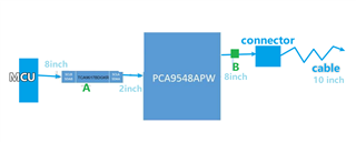
The topology is as shown in the figure, the MCU goes through 9617, 9548 and then through cable to the end device.
Is the 9617 placed (A)before the 9548 to enhance the cable’s signal output from the 9548? Or only placing the 9617 at position B will enhance the output cable's signal?

  • Hi Roy,

    Since this is a question mainly pertaining to TCA9617A impact on the system, I'll loop in the TXP team for insight. 

    From what I can tell, the TCA9617 has impacts in both position A and B. In position A, it can help overcome signal degradation caused by cable resistance and capacitance by buffering the signals and increasing drive capability. Placing this device in position B can help isolate downstream bus capacitance, so placing it in this position can reduce total bus capacitance. 

    Regards,

    Alex

  • Hi Roy,

    I believe the functionality would be the same if the TCA9617A buffer was located on the A-side of the PCA9548A vs. the B-side of the PCA9548A. Normal I2C would function nearly the same on both sides for the placement of the 9617A buffer. PCA9548A is a passive switch. When a channel is enabled from A-side to B-side, the only device separating the two is a passFET. 

    I would recommend that the buffer be placed on B-side, but this would have to comply with your level-translation (if you are using it) between MCU - Switch - downstream target device. I would want the buffer to drive a LOW signal on the output of the PCA9548A, not through the PCA9548A if that makes any sense. The reason being, is that TCA9617A can technically pull 30mA of current if needed due to higher open-drain drive strength required by the fast-mode + standard of I2C. 9617A is able to buffer two bus lengths with 550 pF load cap on each segment. This is problematic for the PCA9548A, since if 30mA were to be drawn for some reason, I believe the buffer would drive enough current to damage the switch. 

    Recommendation is "B" location for TCA9617A. 

    Regards,

    Tyler

  • Thanks Tyler, I would populate 8 *TCA9617A on B-side if the switch 8 channels are used. but 1 *TCA9617A on A-side can also do it. if so, put in A-side, will be cost-effective.

  • Hi Roy,

    This would work as long as your system adheres to the I2C standard for bus capacitance limits. We need to ensure that if all 8-channels have been enabled, that the total parasitic bus capacitance would not go above 400pF for standard/fast mode, or 550pF for fast mode+.

    Regards,

    Tyler

  • Hi Tyler, 

    Yes, we only enable one channel to keep the i2c bus capacitance within the specification.