This thread has been locked.

If you have a related question, please click the "Ask a related question" button in the top right corner. The newly created question will be automatically linked to this question.

DP83TC812EVM-MC: DP83TC812EVM-MC => Does this EVM support SFD IEEE 1588 timestamp

Part Number: DP83TC812EVM-MC


Hello

    DP83TC812EVM-MC => Does this EVM support SFD IEEE 1588 timestamp ?

Please point me the TI Document where it shows that DP83TC812EVM-MC support SFD IEEE 1588 timestamp.

Before I buy this EVM, I need to confirm if this support SFD Detection ? 

Thanks

Krish

  • Hello Krishna, 

    Yes in the DP83TC812 Data sheet: 

    https://www.ti.com/lit/ds/symlink/dp83tc812s-q1.pdf?ts=1706728205781&ref_url=https%253A%252F%252Fwww.ti.com%252Fproduct%252FDP83TC812S-Q1

    IEEE 1588 SFD support is listed 

    Furthermore in section: 

    8.6.2.44 IO_MUX_CFG_1 Register (Address = 452h) [Reset = 0000h]

    You can see the LED_1 and LED_0 GPIO pins can be configured for SFD using the register.

    Regards,
    Avtar

  • Hello Avtar

            Can you please point out the correct Procedure to detect the SFD on DP83TC812EVM-MC. 

    What registers ( address, data) need to be programmed in order to detect the SFD on this DP83TC812EVM-MC.  ?

    As per the following TI Spec ( Section 4, Page 3) , it shows the procedure to detect the SFD on EVMs such as DP83867IRPAP,  DP83867ERGZ-S,  DP83867ERGZ-R.

    How to Configure DP83867 Start of Frame Detect (ti.com)

    I tried same procedure as per the above Spec ( Page 3)  and it does not seem to work with DP83TC812EVM-MC.  

    Can you please  list me the correct procedure to detect SFD specifically on DP83TC812EVM-MC ? 

    Look forward to hear the answer as early as possible as my project is waiting on this.  Thank you so much.

    Krish

  • Hello Krishna,

    The SFD registers for the DP83867 are different than those for the DP83TC812. As I mentioned earlier, 8.6.2.44 IO_MUX_CFG_1 Register 0x0452 is the register for configuring SFD, in the DP83867 it is register 0x0172. That is why it didn't work with the DP83TC812. 

    Here is a rough procedure to detect SFD for the DP83TC812:

    1. Enable enhanced receive features by writing 0x1080 to register 0x04A0 

    2. Configure the device to output the SFD's by writing 0x0406 to register 0x0452

    -this will configure the receive SFD on the LED_0 pin and the transmit SFD on the LED_1 pin

    3. Apply a software restart by writing 0x4000 to register 0x001F

    Please note, registers 0x04A0 and 0x0452 are extended registers and you will need to follow the extended register access procedure in order to write to them. Please follow this FAQ to access these registers: 

    e2e.ti.com/.../faq-extended-register-space-access-for-ethernet-phys

    Regards,

    Avtar

  • Hi Avtar

         Thank you for the Answer and it helped to configure the Board. But, the observing the SFD is not happening.

    The moment that I program those 2 registers (0x04A0, 0x0452) , I observed that The LED_0 is turned ON right away and stays ON and LED_1 was ON for a moment and then turned OFF afterwards.  

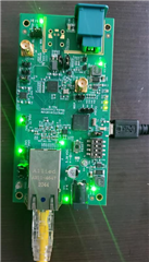
    I did connect the Ethernet Cable to the Board as shown below with the source of incoming ethernet packets.

    When the Ethernet packets are fed into the Board, I expected the LED_0 to blink as per the following statement.

    " this will configure the receive SFD on the LED_0 pin and the transmit SFD on the LED_1 pin"

    But, I do not see any changes on either LED_0 nor LED_1. ( Except the LED_0 is ON forever and LED_1 is OFF from the moment those 2 registers are programmed.)

    Even if I unplugged the Ethernet Cable from the Board, LED_0 is still ON. 

    What does this mean,  even when there are NO ethernet packets are fed into the board.

    The question is how do I observe  the detection of SFD ?  Is there any PINs or  GPIO Registers that I can observe for all the incoming SFDs ? 

    Screen shot from USB-2_MDIO.   I used PHY_ID =10 and Extended Register = Yes.

    Looking forward your answer.

    Thanks

    Krish

  • Hello Krish,

    From what it looks like the test setup is currently Packet generator -> EVM (connected to laptop) 

    The correct setup to detect SFD on the DP83TC812 on the media converter EVM looks like this:

    Packet generator -> EVM #1 -> EVM #2 -> packet generator 

    This is because if you just send packets from one side you are only going to the DP83867 PHY on our media converter board, you will have to connect the DP83TC812 to another DP83TC812 media converter EVM in order for them to link up and traffic to cross. 

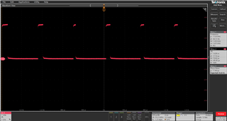
    Also configuring the detection of SFD won't make the LED blink as the packets are going too fast for the LED to turn on / off the LED will look like it stays on. You will have to probe the pin where you will see the detection. Below is what I see when I configure LED_1 to 1588 TX detect: 

    When I stop the packet generator this waveform goes away. Configuring LED_1 to 1588 TX or RX and then probing the pin itself should yield the same results.

    Regards,
    Avtar 

  • Hello Avtar

         Thank for the great responses so far.  Can you pls answer the remaining questions.  

    " Configuring LED_1 to 1588 TX or RX and then probing the pin itself"

    1. Can you pls tell me which PINs that you are referring for probing ?  Pls show it through a board figure.

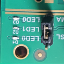
    There are 2 PINs next to LED_1 and LED_0 and these 2 PINs are capped by the Jumper as of now.

    2. I do have Only ONE DP83TC812EVM-MC board with me. 

    Do I really need to buy another similar EVM in order to test the already existing EVM ?  

    Can we test like this without 2nd EVM  ?     

    Packet generator -> EVM #1 -> Scopes and Probes.   ? 

    3. " what I see when I configure LED_1 to 1588 TX detect"

    Can you pls send me a figure showing the connection of EMM to Tektronix Prob as per your testing.

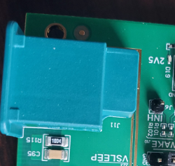
    4. What is the usage of the following output port in the board. ?  What type of connecting plug/cable is supported for this ? 

    Thank you so much for your great answers so far.

    Krish

  • Hello Krishna,

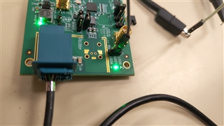
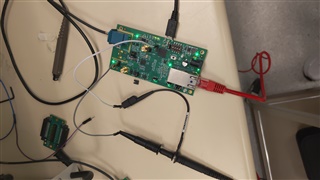
    Hopefully the below two pictures can help you with points 1,2,3:

    As seen above I removed the jumper and am probing the pin that is right next to LED_1.

    As seen above I have connected the ground of the probe to one the ground headers on the board. And then connected the probe to the LED_1 pin. 

    I tried to just use one of the EVM's but it seems like the packet's weren't getting to the DP83TC812 they were stopping at the DP83867 on the board. The only setup I have tested that works is the two board setup which enables traffic to go both ways instead of only one way. I used these registers:

    Register 0452 is: 0405
    Register 0452 is: 0504

    4. So the board we are talking about is the media converter board, there are two connectors on this board one RJ45 connector, and another MATEnet connector. This board converts the standard ethernet from the RJ45 medium to the single pair ethernet through the MATEnet connector. I have attached a MATEnet cable as seen in the picture from one EVM to the other EVM and then on EVM #2 I have attached an ethernet cable back to another packet generator thus closing the loop. So it looks like this Packet generator -> ethernet cable -> EVM #1 -> matenet cable -> EVM#2 -> packet generator. 

    The supporting cable that would support the MATEnet connector would be the MATEnet connecting cable.


    Regards,
    Avtar

  • Hi Avtar

        That was an excellent answer.  That helps a lot. Thank you so much.

    In the last answer, you said 

    "I used these registers:   Register 0452 is: 0405,    Register 0452 is: 0504 "

    Question 1 :  In the above statement, the same register 0452 is written with 0405 and 0504. Why is that ? 

    Isn't that  Register 0452 is written with 0x0406 value as per the following statement ?  

    "Configure the device to output the SFD's by writing 0x0406 to register 0x0452"

    Question 2 : There are 2 PHYs on the Board.

    A )  Are we supposed to configure both DP83TC812 and DP83867 for just to detect SOF ? 

         Because of connecting 2 EVM's back to back in the test setup,  we need to connect both PHYs ? 

          => " Enable enhanced receive features by writing 0x1080 to register 0x04A0 "

          => " Configure the device to output the SFD's by writing 0x0406 to register 0x0452 " 

           The above steps are enough to configure of both PHYs ? If not, Pls let me know.

    B )  Can we ignore the 100Base-T1 portion of the board and configure only DP83867 in order to detect SOF of incoming ethernet packets Only

    Thanks

    Krish

  • Hi Avtar

       Follow up to the previous answers.

    We know that LED_1 shows the SOF of the ethernet packet. 

    I was able to see the SOF on LED_1. That is great.  Could you please answer the following questions.

    1. Does the MATEnet connector on the board also carries the same SOF ( that comes out on LED_1) ?

    2.  If so, Can we connect the MATEnet to a target device ( PC ) to see the same SOF that we saw through LED_1  ?

    3. If the target device has the RJ45 connector, how do we connect this MATEnet  to RJ45.  Are there any MATEnet to RJ45 converter ?

    I could not find MATEnet to RJ45 converter.  Pls let me know if Texas instrument got such converter. 

    Krish

  • Hello Krishna,

    1. No, the MATenet connector isn't like the RJ45 in which there is an LED

    2. N/A

    3. Our Media Converter board does that exactly, converts the standard ethernet media of a RJ45 to a Single Pair Ethernet media of a MATEnet. That is why there are two connectors for the EVM media converter board. 

    Regards,

    Avtar

  • Hi Avtar

         The  board does ( DP83TC812EVM-MC) have one RJ45 and one MATEnet.  But, we need RJ45 as an output in order to send the output Ethernet packet to PC for further processing.

    Are there any converter from MATEnet to RJ45 with TI ?  

    If there is no such converter, then, do you have similar board ( ethernet detection) with 2 RJ45 connectors ( input and output) ?  

    Pls let me know.

    Thank you.

  • Hello Krishna, 

    If you want to use our DP83TC812 PHY  then the only way to have RJ45 as an output would be putting two DP83TC812 EVM's back to back so it would look like this:

    PC -> EVM #1 RJ45 -> EVM #1 Matenet connector -> EVM #2 Matenet connector -> EVM#2 RJ45 -> PC

    We don't have an EVM with 2 RJ45 connectors. 

    Is this what you are looking for?

    Regards,

    Avtar 

  • Hi Avtar

            If I put 2 EVMs back to back, then, there will be additional latency due to the 2nd board.

    For our application requirement, the Detection Time of ethernet packet is important and any additional delay ( due to 2nd board) will impact the results.

    So, using two EVM will defeat the application requirement of latency.   

    How can we check the ethernet packet content going out of MATEnet ?  

    Aren't there any MATEnet to RJ45 converter ? 

  • Hello Krishna,

    I understand that, however I can only assist with issues or questions surrounding our PHY. The only MATEnet to RJ45 converter we have are our media converter boards such as the DP83TC812EVM-MC. 

    Regrads,

    Avtar