Part Number: DS90UB953-Q1
Hello.
We are using the component :DS90UB953-Q1 in our design .
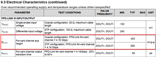
So i am looking for the FPDIII  & Csi
& Csi 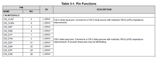 Eye diagrams and Eye Mask receiver standard details for signal integrity.
Regards.
Raneel.
Original question:

Part Number: DS90UB953-Q1
Hello.
We are using the component :DS90UB953-Q1 in our design .
So i am looking for the FPDIII & Csi Eye diagrams and Eye Mask receiver standard details for signal integrity.
Regards.
Raneel.