This thread has been locked.

If you have a related question, please click the "Ask a related question" button in the top right corner. The newly created question will be automatically linked to this question.

TCA9416: Problems with parallel of TCA9416

Part Number: TCA9416
Other Parts Discussed in Thread: TMUX1208, SN74LVC1G34, DRV2605, TCA9617A, TCA9800, TCA39306, LSF0102, TCA9548A

Hello everyone!

I want to bring to you an issue that I am having with a design of mine. 

I want to read from multiple identical devices (I call them Nodes)  that are connected to a single central board (that I call Receiver). The receiver has a 3.3V power, that also supply each of the node. Inside the node, I have a sensor that I want to read from via I2C 1MHz that needs a 1.8V voltage, so I introduced in the node an LDO to go from 3.3V to 1.8V, and a TCA9416 to shift in level the I2C signal. No external pull up resistance in the node.

In the receiver the SDA line is multiplexed using a TMUX1208, and the SCL instead is given to all the nodes (up to 20) using a buffer SN74LVC1G34.

Now, the problem is that I'm having a really hard time to successfully communicate with my nodes: so far, it work only when just one node is connected to the receiver. 

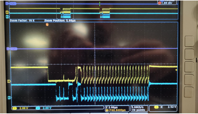
This is what I see when I plug 10 nodes

With 2 nodes instead I see

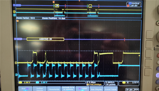
I can see some communication, but overall is unreliable

To isolate the problem, I also tried other devices than the node, and I can see that for example if I plug tw DRV2605 (4.7kOhm pull up resistor) instead of my node, without any TCA9416, I can communicate correctly with both of them without any issue.

Is there anything related to the TCA9416 that can bring this behavior, when the SCL sees a parallel of them? Are there any other suitable devices that It may be worth trying instead of the TCA?

  • The TCA9416 has internal pull-up resistors and edge accelerators. All pull-up resistors are in parallel. The edge accelerators trigger on what looks like the beginning of a rising edge, which can lead to oscillations when there is ringing on the lines; the TCA9416 does not work well with long traces/connectors/cables.

    The TCA9617A/B would not work because you cannot connect its B sides together.
    Do you really need 1 MHz? With 400 kHz, you would be able to use the TCA9800.

  • Hi Clemens, thank you for your answer.

    Yes, the 1 MHz is a requirement.

    I was also having a look at TCA39306. Maybe it's something suitable? Even tough I don't see many difference wrt the TCA9416 apart from internal pullups and edge accelerators. Maybe I couple the TCA39306 with another buffer for SCL in the node, and a somehow bidirectional buffer for SDA in the node?

  • There are very few bidirectional buffers, and they do not work well at high frequencies.

    You can use passive switches like the TCA39306 or LSF0102, but you have to consider the total bus capacitance.

    I would recommend combining the mux and level shifter with something like the TCA9548A, but it can only do 400 kHz. Your 1 MHz requirement is hurting your design.

  • Actually In the previous iteration of this project I was able to run another setup with 1Mhz, in which:

    - In the receiver I have, sequentially:  a TCA9418 to bring down the I2C line from 3.3V to 1.8V followed by a TMUX1208 to multiplex the SDA, while for the SCL I introduced just one buffer.

    - In the node I have everything working at 1.8V supplied by the Receiver. For the I2C lines, just two pull-up resistors.

    We wanted to go towards a 3.3V line design so that we suffer less from voltage drop in case the cable is too long or resistive.

    So I don't really know what is the component that is causing so much trouble. My guess is the N parallel of TCA9416 that SCL sees, but that is really just a guess, it still wouldn't explain it clearly what is happening.

    EDIT: I also wanted to add that I also had to add a small 22 ohm resistor in series of the SDA incoming in the node before the TCA9416 to make the transmission work: otherwise I wouldn't be able to communicate at all, even with just one node

  • The TCA9416 is a passive switch with rise-time accelerators. Try a plain passive switch like the TCA39306 or LSF0102.

  • Hey Dario, 

    The TCA9416 rise time accelerators help reduce rise times to support higher data rates, but can also backfire if the capacitance on the bus becomes too large. Once the rise time accelerators time out, the reflected signal after the transmission line will see a different impedance (10kohms from the high-keepers), hence the reflection. Please try the TCA39306/ LSF0102 (though these devices would require external pullups) as Clemens' has pointed out and see if issue mitigates.  

    Regards,

    Jack 

  • Thank Jack,

    this starts making a bit of sense.

    With the TCA39306 I see that in the use cases (first pages of the data sheet) VREF1 < VREF2, where the 1 side is the controller side, even tough later in the datasheet it says "The TCA39306 is a dual bidirectional voltage-level translator compatible with I2C, SMBus, and I3C with an enable (EN) input, and is operational from 0.9-V to 3.3-V VREF1 and 1.8-V to 5.5-V VREF2."

    Assuming that the "correct" way is to have VREF1 < VREF2, In my use case instead, I would have the controller attached to the 2 side, since I want to output at 3.3V and step down to 1.8V. Is this actually possible or I'll face something weird that makes the system unusable?

  • I²C is bidirectional. The two sides are perfectly symmetrical, but the EN/200 kΩ circuit must be at the high-voltage side. (And you could just rotate the chip.)

    The TCA39306/LSF0102 datasheets describe what the restrictions are (a minimum difference between VREF1 and VREF2, no pull-up voltage smaller than the lower reference). Please note that VREF1/2 are not power supplies but analog biasing voltages.

  • Thanks Clemens. 

    I'm reading about LDOs and TCA39306. In my design, I have the TPS7A0518PYKAR LDO giving me the 1.8V. Should I place a resistor to sink current from Vref2 to Vref1? Or am I good? How do evaluate the sink current?

  • The current flowing into Vref2 and out of Vref1 is limited by the 200 kΩ resistor. (And there might be some leakage current.)

    Are there any other devices connected to the 1.8 V supply that would sink the current? Anyway, any resistor less than 180 kΩ would be enough.

  • I supply the following devices with the 1.8V LDO:

    - BHI260AP

    - BMM150

    - BMP390

    - Flash memory W25Q32JWBYIQ

  • Hey Dario,

    I would recommend having an additional pulldown on the LDO side to sink the leakage current (assuming VREF2 = 3.3V and VREF1 = 1.8V), the leakage current that the LDO will see is about (3.3-0.7)/200k = 13uA. The pulldown resistor value for the LDO node that Clemens' mentioned should suffice. 

    Regards,

    Jack