This thread has been locked.

If you have a related question, please click the "Ask a related question" button in the top right corner. The newly created question will be automatically linked to this question.

DP83869HM: DP83869HM 100M media converter continuous transmission of unknown signal from TD pins

Part Number: DP83869HM
Other Parts Discussed in Thread: DP83869EVM, DP83869

Dear TI, 

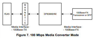
We have DP83869HM configured as 100M media converter. 

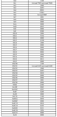
When connected to PC from copper side, link comes up and registers readings show healthy values at all times. 

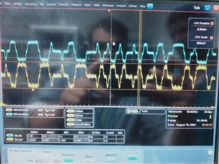
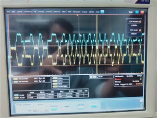
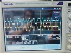
The problem is as soon as auto negotiation completes and link comes up successfully, DP chip begins sending continuous MLT-3 “junk” from TD0 and TD1 pins towards the PC. 

 Kindly discuss internally and please provide a clue as to what operating condition(s) of DP83869HM such event occurs ?

 Attached are scope screenshots for TD0 and TD1 probed  single-ended for more clarity. 

Does anyone recognize those patterns ? 

Regards

Sanju

  • Hi Sanju,

    I need to discuss this with the team. Please expect a follow-up on Monday 2/5.

    Thank you,

    Evan

  • Hi Sanju,

    The PHY is expected to send out MDI signals during idle to indicate to its link partner that the link is still active.

    Please let me know if there are any link or communication issues that I can help debug.

    Thank you,

    Evan

  • Dear Evan,


    Thank you for your response,

     Attached are some register readings for your kind review.  Registers 1h and C01h are read twice for valid value as per datasheet. 

    Please let me know if you see anything abnormal. 

     SO_(P/N) pins show repeating 01 pattern at 125MHz (8ns pulses). 

    When we send traffic via the copper side, we expect to see non-repeating binary patterns at SO_(P/N) pins, but we don’t. 

    That is the problem. 

    The repeating 01 patten at SO_(P/N) never stops. 

     We really need your expert assistance to overcome this problem. 


    Your kind response is very important,


    Regards,

    Sanju

  • Hi Sanju,

    Thank you for sharing the register dump and further details on the issue.

    Can you share a block diagram with the intended signal chain?  It's possible the device is not set in the correct mode, is this the intended signal chain?

    The registers indicate link up without any errors.

    Thank you,

    Evan

  • Dear Evan,


    Thanks again for your prompt response. 

     Yes, our topology is as per figures 7 and 9-12 relative to the datasheet. 

     Evan, in this case, it would help a lot if there was copper side  Tx/Rx packet counter on the DP chip registers ? 

    There could be such counters probably on undocumented registers?

     This will help us big time. 


    Best wishes,

    Sanju

  • Hi Sanju,

    Unfortunately, there is only a packet counter available when using PRBS generator/checker.

    Do you need a packet counter for application-level logic, or only for debug/evaluation stage?

    Thank you,

    Evan

  • Dear Evan,


    Yes, we are trying to trace packets sent from PC to DP chip with a simpler method than going into loopback scenarios. 


    May I ask you the following:

    Would you please replicate datasheet’s figure 9-12  topology on your side as 100M media converter with two PC’s as the end devices. 

    If you manage to perform a successful ping then we could check back our setup and compare it to your successful setup. 


    If you decide to do the above , then we would very much appreciate the following from your experiment:


    1- register dump;

    2- NIC make and model of each endpoint;

    3- endpoint (PC) IP setup; and

    4- schematics if possible. 


    This way we will compare your design with ours and make necessary changes. 


    I believe this will help us and many other viewers. 


    Regards,

    Sanju

  • Hi Sanju,

    Sounds good! I will replicate the setup and share the schematic & configuration details.

    It will take some time, please expect a follow-up before Tuesday 2/13.

    Thank you,

    Evan

  • Dear Evan,

     Super! Thank you. Looking forward to Tuesday. 


    Some info for you:

    Please note that we used intel i219V as the network adapter on our PCs (driver updated to latest release). 

    We also used CAT5e between DP and PC. 

    PCs had static IPs. 

    DHCP turned off. 

    Direct PC to PC (without DP) ping works. 


    Meanwhile, I have a quick question for you:

     In all our attempts, the only thing we didn’t like in our registers dump was register Ah. 

    It should have read as 3800 but in every test attempt it was showing a value of 0800. 


    In your DP chip design, is local receiver status (ok not ok) part of 100M media converter requirements? Or is it only important in 1G media converter mode?

     According to the attached image, and from what we are seeing, MLT3 alive signal is going to its intended route thus link is up. But when it comes to TCP/IP traffic, it seems that data is stopping at the receiver block (receiver not ok in our case as register Ah reads 0800). 

    What is your opinion on that ?


    Many thanks,

    Sanju 

  • Hi Sanju,

    Thank you for clarifying the system configuration.

    I'm uncertain if the receiver status bits Ah[13:12] correspond directly to link up/fail. I will share these bits in the full register dump after replicating the setup.

    Thank you,

    Evan

  • Hi Sanju,

    Unfortunately I ran into some setup issues while attempting to replicate the configuration in lab. I will continue and look to have an update for you tomorrow.

    Apologies for the delay,

    Evan

  • Thanks Evan,

    Will be waiting for you..


    Meanwhile, for your information, on our setup wire shark shows packets (of which unicast and broadcast packets) have been sent via the PC interface and travelled through the wire. 

    Whereas, at the same time, register 135h is not showing any unicast or broadcast packets received. 

    After successful link up, packets sent from PC to DP chip seems to be lost inside the DP chip and not reaching SO_P SO_N in 100M media converter mode. 


    Regards,

    Sanju

  • Hi Sanju,

    I have replicated the setup on DP83869EVM, set in 100M media converter mode as follows:

    Network switch <- Fiber 100M -> DP83869EVM <- Copper 100M -> PC

    Network switch is set to force 100M on fiber connection. PC and DP83869EVM have auto-negotiation with all advertisements enabled.

    Network switch has IP 192.168.100.100 , PC has IP 192.168.100.101 on ipv4 adapter.

    Here is the resulting register dump:

    Register 0000 is: 3100
    Register 0001 is: 796d
    Register 0002 is: 2000
    Register 0003 is: a0f3
    Register 0004 is: 01e1
    Register 0005 is: cd81
    Register 0006 is: 006d
    Register 0007 is: 2001
    Register 0008 is: 4806
    Register 0009 is: 0000
    Register 000a is: 0000
    Register 000d is: 401f
    Register 000e is: 0000
    Register 000f is: f000
    Register 0010 is: 5848
    Register 0011 is: 6c02
    Register 0012 is: 0000
    Register 0013 is: 0000
    Register 0014 is: 29c7
    Register 0015 is: 0000
    Register 0016 is: 0000
    Register 0017 is: 0040
    Register 0018 is: 6150
    Register 0019 is: 4444
    Register 001a is: 0002
    Register 001e is: 0012
    Register 001f is: 0000
    Register 0c00 is: 2100
    Register 0c01 is: 614d
    Register 0c02 is: 2000
    Register 0c03 is: a0f3
    Register 0c04 is: 0020
    Register 0c05 is: 0000
    Register 0c06 is: 0000
    Register 0c07 is: 2001
    Register 0c08 is: 0000
    Register 006e is: 3a00
    Register 01df is: 0005
    Register 01ec is: 1ff5
    Register 004f is: 0200
    Register 002d is: 0000
    Register 0c10 is: 3148
    Register 0032 is: 0050
    Register 006f is: 0000
    Register 0c19 is: 0000
    Register 0c18 is: 01ff
    Register 002e is: 0221
    Register 0c30 is: 3056
    Register 0135 is: 0000
    Register 0030 is: 0000

    With this setup, ping is working and there are no communication issues. Register 0xAh is not a consistent reference for link status for this configuration.

    The schematic files are available here: https://www.ti.com/tool/DP83869EVM

    Network switch: https://www.artel.com/media-transport-products/quarra-1g-compact-ptp-ethernet-switch/

    Please let me know if I can clarify any of the setup details.

    Thank you,

    Evan

  • Dear Evan,


    Your data is very valuable. Thank you. 


    It looks like register dump provided by you was 2nd read of registers as some registers were cleared after 1st read and other usually change value after the first read such as registers 6h, 11h, 13h and some other LED related. 

    The above difference are not very important in my opinion. 


    But the Important differences are:


    1- Your PC (Copper link) did not advertise for 10mbps. Probably that’s not important. 


    2- Bit 14 of register 6E is high in your case. It’s 0 in my case. Is that important?


    3- I think the most important is Bit 11 of register 8h. In your case this bit is 1 (which is right according to section 28 of IEEE 802.3u Toggle bit section). But in our case it’s 0. We tried putting an unmanaged 100M switch between the PC and the DP. No change, register 8h = 4006 in our case where it should be 4806 as in your case or better still 6801. 


    Please help with the 3 observations above. 


    Regards 

    Sanju

  • Dear Evan,


    This is a follow up to my latest response.


    I’ve tried forced 100M full duplex just to bypass auto negotiation (in case it’s the problem). 

    Link came up but no traffic. Same problem. 


    So far in all 100M scenarios we tried, including your scenario, the following is observed:


    1- link is up, but the two PCs within same subnet don’t see each other. They only see each other when we connect PCs directly. 


    2- in register 13h, in most cases; MDI crossover flag comes up whether straight or crossover CAT5e is used, or whether manual or auto MDI is set. 


    Would you please provide further advice based on the observations above ?


    Regards 

    Sanju

  • Hi Sanju,

    I will review and get back to you with next steps. At the latest, I will have feedback by Tuesday 2/20 due to U.S. holiday.

    Thank you,

    Evan

  • Dear Evan,


    Follow-up:

    The problem is now reducing to:


    Case 1: Direct PC A to PC B link:

    PC A is on private network. 

    PC B is on private network. 


    Case 2: PC A to PC B link in our setup as per figure 9-12 of datasheet:

    PC A is on private network. 

    PC B is on unidentified network.


    We tried to identify the unidentified network with no luck.  It always reverts back to unidentified network. 


    We tried swapping positions of PC A and PC B. Same outcome, PC B remains on unidentified network. 


    We tried replacing PC B with different laptop and Desktop as PC B. Still no change PC B is on unidentified network. 


    Conclusion:

    Both PCs are healthy and on private network when directly connected. 


    However, when back to back media converters are in between the PCs (as per figure 9-12) one PC is okay on private network and the other is always on unidentified network. 


    Unidentified network is not good. 

    Unidentified network cannot see gateway (though gateway is set.. please see attached images of PC B). 


    Link loss pass through is enabled and end to end link is up always. 

    Physical layer is okay, problem on data link layer. 


    Any suggestions at this stage Evan?


    Regards 

    Sanju

  • Hi Sanju,

    2- in register 13h, in most cases; MDI crossover flag comes up whether straight or crossover CAT5e is used, or whether manual or auto MDI is set. 

    This may due to the RJ-45 internal pin mapping reversed between our setups. Please try enabling mirror mode via straps (pin38 PU) or through register 0x31[0] = '1'.

    Could you clarify how you are seeing no traffic between link partners? Have you tested with iperf for throughput measurements, or another method?

    1- link is up, but the two PCs within same subnet don’t see each other. They only see each other when we connect PCs directly. 

    Please share the IP address and gateway settings for both PCs you are testing with. I would like to replicate the setup again, is this correct:

    PC1 <- 100M copper -> 869HM <- 100M Fiber -> Network Switch <- 100M copper -> PC2

    Thank you,

    Evan

  • Hi Evan,


    Tried mirror mode sometime ago. It didn’t help. 


    As for traffic, we send continuous ping -t t from PC to DP and we probe SO_(P/N) via scope and we set scope to capture any pulse wider than 8ns (125MHz). If there is traffic’s c then SO_(P/N) output will be non repeating 01  where normal traffic will have many consecutive 1s or 0s wider than 8ns. Meaning traffic is passing.  However, the unidentified network issue narrowed the search for the problem. If it is fixed then it could solve everything. 


    Regarding IP setup, I shall pass it in the next post as I am preparing for you. 

    Please note that Windows Defender is disabled on both PCs. 


    Will post required setup soon


    Regards 

    Sanju

  • Dear Evan,

    find the below PC Set Up

    1- Topology under Test (near end is PC A and far End is PC B). We are using two DP boards. 


    2-  PC A:

    IP: 192.168.1.3

    Gateway: 192.168.1.2

    Mask: 255.255.255.0


    3- PC B:

    P: 192.168.1.2

    Gateway: 192.168.1.3

    Mask: 255.255.255.0

    4- Routing table on PC A:

    5-  Routing table on PC B:

    6- PC A Netstat 

    7- PC B Netstat 

    Regards,

    Sanju

  • Hi Sanju,

    Thank you for sharing the setup details. I suspect the issue is on the application-level rather than the PHY-level.

    I will look to replicate the setup and see if I can have successful ping and throughput tests between PCs.

    Please expect feedback by 2/22 at the latest.

    Thank you,

    Evan

  • Hi Sanju,

    While I work on the setup, please try this test:

    - Link loss pass through enabled, plug / re-plug RJ-45 on DP83869

    - Link loss pass through disabled, plug / re-plug RJ-45 on DP83869

    Do you see any difference in behavior for either case?

    Thank you,

    Evan

  • Dear Evan,


    Our bootstraps setting kept LLPT disabled. 

    We have also tried enabling it post bootstrap latching by register 01ECh. 

    Looks like it’s working whether LLPT is enabled or disabled. 

    Evidence on that: whenever we cut the incoming 01 signal (FROM SO_(P/N) to SI_(P/N) in either direction) links between PCA and Board A, plus PC B and Board B; goes down. 


    So far, we found that a PC with Windows 11 build #22000.1936 is okay. 

    We tried newer builds of Windows 11 plus various builds of Windows 10, they all result in the unidentified network problem. 


    We are now trying to make PC A and B both as the same build #22000.1936 (Noting that this build # is no longer supported by the Maker). 


    Once we manage to unify the OS build as explained above, things will be clearer.  Will keep you posted. 


    In the meantime, have you tried replicating datasheet’s figure 9-12 in 100M media converter mode with far end and near end being both Windows 11 PCs ?


    For near end and far end PCs, what are the tested operating systems for reliable link with DP board. 


    Many thanks for your continued support,


    Regards 

    Sanju

  • Hi Sanju,

    We unfortunately only have Windows 10 and Linux machines available to replicate the setup - is there value for you in replicating the setup with back to back Windows 10 PCs?

    I've tested with Linux, Windows 10, and managed switches for successful ping/iperf between LPs through DP83869.

    My best guess is the OS-dependent issue may come from native firewall settings - there was a past case where applying this configuration resolved ping issues on another PHY for Windows 11:

    https://superuser.com/questions/1683853/cannot-ping-a-windows-11-machine

    Please let me know if this helps.

    Thank you,

    Evan

  • Dear Evan,


    Tried your lead. No change so far. 


    Please hold on until Tuesday we may have more info for you by then. 

    We are still working on PC B. 


    Thank you for your patience. 


    Regards 

    Sanju

  • Hi Sanju,

    Thanks for confirming.

    Curious to hear updates when you have more information.

    Best regards,

    Evan

  • Dear Evan,


    Apologies for the delay. We need a couple more days. Please keep this thread open. 

    Thank you for your patience. 


    Regards 

    Sanju

  • Hi Sanju,

    No worries, looking forward to hearing updates.

    Thank you,

    Evan

  • Dear Evan,


    Would you please provide the make and exact model of each of the Linux and Windows 10 machines used in your test ?


    Furthermore, it would be super if you can provide extra info about the make and model of Ethernet adapters of the two machines you used. 


    Much appreciated,

    Sanju 

  • Hi Sanju,

    Sure, here is the information I have access to now:

    OS: Microsoft Windows 10 Pro

    Version: 10.0.19045 Build 19045

    Model: HP Probook 640 GB Notebook PC

    Ethernet adapter:  Intel(R) Ethernet Connection (13) l219-LM

    I unfortunately do not have access to the Linux machine until Tuesday 3/5, will share details for that machine then.

    Thank you,

    Evan

  • Please see Linux machine information below:

    OS: Ubuntu 18.04.6 LTS

    Ethernet adapter: Intel I219-LM (rev21)

    Thank you,

    Evan

  • Dear Evan,


    Thanks for your latest post and apologies for the late response. 


    We have rectified everything regarding PC_A and PC_B.

    There are no issues now with near end (PC_A) and far end (PC_B). 


    The issue is back to the DP83869. 

    SO_(P/N) outputs continuous <01> no matter what we do. 

    Once again, either the 100Base-TX is not passing anything to the 100Base-FX module. Or the 100BaseTX is passing traffic to the FX module but the FX module maybe being in permanent idle state. 


    Evan, we really need your in-depth help please. We may also need some assistance from DP83869 chip designers. 


    Please help. 


    Regards,

    Sanju

  • Hi Sanju,

    Glad to hear everything is okay on PC end.

    Please share the schematic with me so I may review (email to e-mayhew@ti.com for private share).

    Also, please confirm if there are any differences in the current register dump values relative to the initial dump shared.

    Thank you,

    Evan