This thread has been locked.

If you have a related question, please click the "Ask a related question" button in the top right corner. The newly created question will be automatically linked to this question.

DS16F95QML: Polarity Issue for A, B, Positive, Negative

Part Number: DS16F95QML
Other Parts Discussed in Thread: DS26C31MQML, DS16F95, DS26LV31QML

Dear design support team.

I am confusing RS485 interface polarity.

According to TIA-485-A, when VA - VB is positive, the logic value is "0". this means B > A in Mark (Idle, logic ="1") and A > B in Space (On, logic ="0").

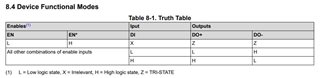
but, TI parts are logic value "1" when VA -VB is positive and it is higher 200 mV.

The logic value mentioned above means "DI" or "RO".

I know your method or definition is more common, but I'm curious as to why.

Could you please explain or this issue? I would like a detailed description.

Thank you for always.

  • Wikipedia says:

    The RS-485 differential line consists of two signals:

    • A, which is low for logic 1 and high for logic 0 and,
    • B, which is high for logic 1 and low for logic 0.

    Because a mark (logic 1) condition is traditionally represented (e.g. in RS-232) with a negative voltage and space (logic 0) represented with a positive one, A may be considered the non-inverting signal and B as inverting. The RS-485 standard states (paraphrased):

    • For an off, mark or logic 1 state, the driver's A terminal is negative relative to the B terminal.
    • For an on, space or logic 0 state, the driver's A terminal is positive relative to the B terminal.

    The truth tables of most popular devices, starting with the SN75176, show the output signals inverted. This is in accordance with the A/B naming used by most differential transceiver manufacturers [Intersil, Maxim, LT, AD, FTDI].

    These manufacturers all agree on the meaning of the standard, and their practice is in widespread use. The issue also exists in programmable logic controller applications. Care must be taken when using A/B naming. Alternate nomenclature is often used to avoid confusion surrounding the A/B naming:

    • TX+/RX+ or D+ as alternative for B (high for mark i.e. idle)
    • TX−/RX− or D− as alternative for A (low for mark i.e. idle)
  • Thanks for your detailed answer.

    According to your answer, The A terminal of DS16F95QML corresponds to (-), and B terminal corresponds to (+).

    And I understood the "For an off" in your answer is state of "DI" of "RO" terminal.

    But, I am still confused.

    Because, I use DS26C31MQML and DS26LV31W.

    According to this part datasheets, DS26C31MQML [DO 1(+)] and DS26LV31W [Non-Inverting] correspond to DS16F95QML [A terminal]. (in terms of them truth table).

    For quickly understanding, Let's assume that DS26C31 and DS16F95 need to be electrically interfaced(connected).

    where should [DO 1(+)] of DS26C31 be connected to DS16F95?

    according to them truth tables, DO 1(+) should be connected to A terminal of DS16F95. Is it correct?

    then, where are the  "TX+/RX+ or D+ as alternative for B" you mentioned are applied or used?

    Thanks

  • It does not matter how you name the pins; ignore the names. (And the DS26C31MQML datasheet does not even give the pins names.)

    As shown in their datasheet, on the DS26C31MQML, the pins 2, 6, 10, and 14 are non-inverting; on the DS16F95QML, pin 6. Connect them together.

  • Thanks for answer.

    I am sorry,  DO 1(+)  in my question was about for DS26LV31QML.

    As you said, I will ignore the pin name and follow the schematic.

     in DS26LV31QML

  • Hi Daejin,

    Do you still have questions about this? Table 8-1 in the datasheet provides a truth table of the pin states.

    As long as you tie the differential output pins to the receivers pins (non-inverting to non-inverting and inverting to inverting) then you shouldn't have any issues with polarity. 

    DO 1(+) should be connected to A terminal of DS16F95. Is it correct?

    then, where are the  "TX+/RX+ or D+ as alternative for B" you mentioned are applied or used?

    In your example. DS16F95 has pin labeled B as the inverting pins and A as the non-inverting pins. 

    So DS26LV31 D01+ would connect to DS16F95 A and DS26LV31 D011 connects to  DS16F95 B.

    then, where are the  "TX+/RX+ or D+ as alternative for B" you mentioned are applied or used?

    These names aren't being used by the datasheets you have referenced. But Tx+/Rx+ would be D0 + or A and Tx-/Rx- would be D0 - or B.

    -Bobby