This thread has been locked.

If you have a related question, please click the "Ask a related question" button in the top right corner. The newly created question will be automatically linked to this question.

DS90UB924-Q1: Serial control bus register setting

Part Number: DS90UB924-Q1

Hi team,

It has been confirmed that the red line is generated in monitor on the customer side. This occur about 20 times in 6000 times by repeating the operation ON 4s to OFF 5s. The controller side is always on.

Ser/Des: 925/924

They changed Path-Through register 1 to 0(default), this problem was solved.

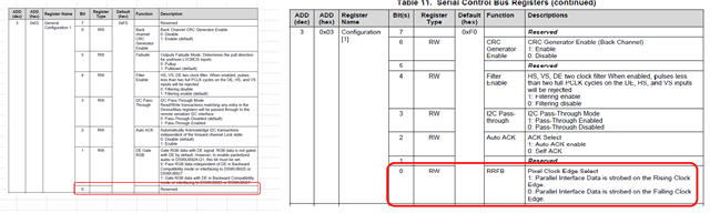
What effect does setting the Reserved flag to a value that is not a Default have on FPD link Ⅲ to OLDI conversion? 

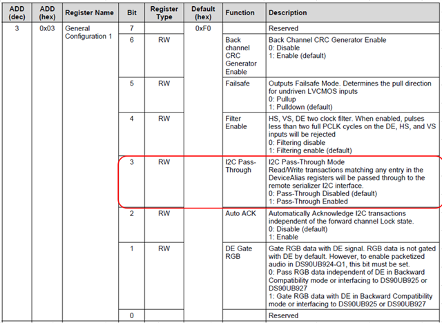
Is the Pixel clock edge setting in the register map of 926, but is the same set up/hold done during FPDLINK Ⅲ => OLDI conversion in the Reserved part of 924?

Regards,

Youhei MIYAOKA

  • Hi Youhei,

    Just to clarify: the issue was red line occurring on some displays. And disabling the passthrough solved the issue? By changing 0x03[3] = 0?

    Was there any MCU or devices connected to the 924 I2C? What remote I2C devices are connected here? Why did customer choose to change this setting to solve this issue??


    The reserved bit 0x03[0] should not be changed. The 924 and 926 devices are for different video interface outputs.

    Best regards,
    Ikram


  • Hi Ikram,

    Just to clarify: the issue was red line occurring on some displays. And disabling the passthrough solved the issue? By changing 0x03[3] = 0?

    Yes. And my customer want to know the reason.

    Was there any MCU or devices connected to the 924 I2C? What remote I2C devices are connected here? Why did customer choose to change this setting to solve this issue??

    Let me confirm to the customer, wait for their feedback.

    Regards,

    Youhei MIYAOKA

  • Hi Youhei, 

    Thank you. Please provide more information about the system:

    1. What operational modes are used for the 924 and 925 pair? What devices are connected via I2C? Please share the topology of connected devices (display, remote devices, MCU/SoC host, etc) and the addressing used

    2. Is this for a custom board or using TI EVMs? Is the issue reproducible with certain boards? Is it following the DES or SER boards? How many systems were tested?  

    3.  A register dump of the working and not working (red line issue) devices would be helpful. Please also share the initialization script used

    Best regards,
    Ikram

  • Hi Ikram,

    Here is customer comment below. Could you answer for the last sentence?

    The only device connected to the 924's I2C is the MCU.
    There is a model that originally used 926,
    I was using Pixel Clock Edge Select bit with 1.
    This is because the above register was not set to 0 on the 924 model.

    Therefore Please let me know if changing the 924 Reserved register from 0 to 1 will affect the output OLDI.

    Regards,

    Youhei MIYAOKA

  • Hi Youhei,

    Thank you for getting back about this. The reserved register should not be changed to 1. 

    As for the red line issue, could you please share the operational modes and topology used. Also, to narrow down the issue, could you please try using the 925 internal PatGen to check whether the issue occurs. 

    The 926 and 
    As for the issue with red line,