Part Number: TCAN1051HG
Other Parts Discussed in Thread: SN6501
Hello TI team,
I need to implement an isolated CAN Bus node, but I am not sure how to determine the power needed for the isolated 5VDC power supply. From what I am seeing, there are many ways to implement an isolated circuit;
1) Power isolator, signal isolator and regular CAN transceiver (cheaper solution).
2) Power isolator and isolated CAN transceiver.
3) Isolated CAN transceiver with integrated power isolator.
Question 1
No matter which solution I choose, I always have the same question. What is the maximum current drawn on the isolated power supply? Let’s say solution 1 is chosen (because it tends to be cheaper);
- DC/DC converter: TI part UCC12040DVER
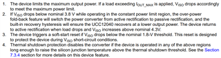
Even though the spec indicates that this module can be used for isolated CAN transceiver application, the output power seems to be inadequate (the following paragraphs will show the calculation). As per the spec sheet, at a temperature of 105C, the VISO current is limited 85mA (VINP = 5V, 105C). The VINP needs to be increased to 5.5VDC to get more current. Is that right?
- Regular CAN Transceiver: TI part TCAN1051HGDR
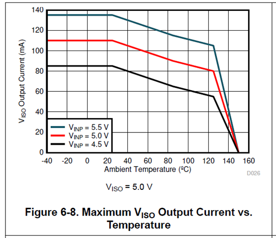
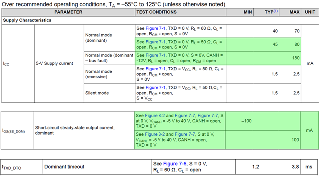
From the spec sheet, the regular CAN communication draws 45mA (max 80MA), using an equivalent termination of 50ohm. A short circuit to -12V on CANH will draw 180mA, but for a limited time, determined by the TXD Dominant Timeout (DTO) of 1.2ms. A short circuit to -5V/40V on CANH will draw 100mA, also for a limited time determined by the TXD Dominant Timeout (DTO) of 1.2ms. I have tried here to use the average short circuit current that would be flattened out to a lower value (by the bus that switches between dominant and recessive states), but for the estimated power calculation, I think I need to use the instantaneous current, right?.
I(transceiver) = 180mA (Normal mode (dominant – bus fault)
I(transceiver) = 100mA (IOS(SS_DOM))
(And if I used an average short circuit current I(transceiver) = 28.8mA, using formula in the spec sheet)
I(transceiver) = 80mA (Communication Normal Mode max)
Which current is good? The power budget is very limited (500mW), and if the current is too high, the short circuit protection of the DC/DC converter will be triggered. The following are snapshots of the spec where I took the values listed above.
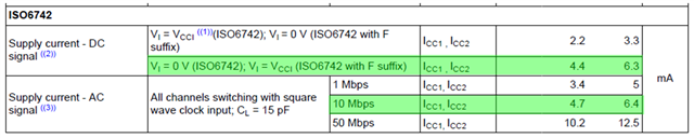
- Quad Signal Isolator: TI part ISO6742DWR
Two channels are used on the Quad digital isolator for the isolated bidirectional communication between the CAN transceiver and the CPU CAN controller. Also, one channel is used for isolated control of the Silent Mode pin of the CAN transceiver. One channel is unused with the input tied to GND2 on the VCC2 side. From the spec sheet, for the CAN FD communication speed, I get 6.4mA max for 4 channels, therefore 6.4mA/2 for two channels. For the other two discrete signals, I get 6.3mA max for 4 channels, therefore 6.3mA/2 for two channels.
I(Isolator)= 6.4mA/2 +6.3mA/2 = 6.4mA max
Therefore, the DC/DC should be current rated to a minimum of
ITotal = I(transceiver) + I(Isolator) = 180mA +6.4mA = 186.4mA
For this current, the UCC12040DVER is underrated, since it can only deliver 85mA @105C. So
- Is my analysis wrong? I have the same problem if I use the transformer driver SN6501, which the propose circuit with transformer is output current limited to 100mA, but recommended by TI for this application.
- The CAN transceiver will protect the output in 2 ways; using the DTO or limit the current on the CAN driver. Do I let the CAN Driver limit the output current or do I let the DC/DC converter fall back to over-current or hiccup mode?
- Should I increase the rating of the DC/DC converter to 1W (200mA)?
Question 2
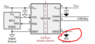
Since the CAN bus is isolated, how are the other nodes able to read the differential voltages across CANH and CANL? These are floating voltages that do not share the same ground. Do I need to provide and connect the isolated ground to the ground of the other nodes through a cable shield or something else?
Thank you,