This thread has been locked.

If you have a related question, please click the "Ask a related question" button in the top right corner. The newly created question will be automatically linked to this question.

SN65LBC180A: PCN details

Part Number: SN65LBC180A

Hi team,


My customer would like to check the PCN# 20230112001.1 details.
In the previous datasheet before the PCN, the thermal information was not shown.
Is the thermal table on new datasheet applicable to the SN65LBC180A shipped before the PCN as well?

Best regards,
Kazuki Itoh

  • The new SN65LBC180A uses a completely different die, so the thermal parameters have changed. In any case, the new device is likely to have a lower power consumption.

  • Hi Itoh-san,

    No the thermal parameters are not the same - but we didn't specify them in the old datasheet. This is new added information - please see explanation I gave on related thread of yours (I understand its about a different part but the analysis/reasoning is the exact same) https://e2e.ti.com/support/interface-group/interface/f/interface-forum/1322941/sn75als176b-pcn-details 

    Best,

    Parker Dodson

  • Hi Clemens-san, Parker-san,

    Thank you for your support.
    You told me that the new device is likely to have a lower power consumption.
    But it's not specified in the PCN.
    Could you provide the data to make sure the lower power consumption?
    Also, is it possible to specify the lowered power consumption in PCN and datasheet?

    Best regards,
    Kazuki Itoh

  • Hi Itoh-san,

    For the newer device power consumption - we do have a graph that we added - figure 5-2 shows new material power performance (it is loaded - so it includes ICC + IOUT + I_AC_Loss (some power current is lost due to output frequency). This is the only data we will provide as this is a typical performance change - but the electrical spec table will remain the same. 

    No we won't add that to the PCN because old material still exists so the datasheet will remain bounded by the old material specs as it is possible to have older material soon.

    Best,

    Parker Dodson 

  • Hi Parker-san,

    You mentioned all the typical values have changed in the other thread.

    Has the typical values in electrical spec table changed? Or remain the same?

    Best regards,

    Kazuki Itoh

  • Hi Itoh-san,

    So the typical values on the new material are most likely going to be different than old material - but we don't generally change the typical value as listed in datasheet for a few reasons:

    1) they aren't really a strict guarantee like our boundary conditions (min/max); they are more there as a reference to show "what could happen" - but ultimately the design needs to be able to handle the min/max conditions which both old and new material conform to (this means that if the proper design protocol happened both devices should be interchangeable)  

    2) The "weight" of the typical values really should be taken with a lot of skepticism in the first place because ultimately "typical" is an average value as measured at 25C and for RS-485 the highest nominal voltage supply - but we don't give variance or std. deviation from that average value so "how likely" that value may occur is not known with typical  (this is the same for pretty much any semiconductor datasheet unless they provide full statistical values which I haven't really ever seen). That's not to say the typical value doesn't have any value to a design as they can be used to make quick approximations - but ultimately design must conform to max/min boundary conditions. 

    3) We still have older material that is in circulation (customers having unused stock of old material, third party resellers, etc....). Since no typical value we put is going to represent the entirety of our current stock in circulation - we tend to move towards "least amount of changes to spec tables as possible" as changes to the spec table generate more concern from end users than typical value changes. That's not to say we don't get questions on the typical values shifts when seen - but ultimately they shouldn't equate to actual application issues because both variants of the material are bounded in the same way. 

    4) Finally we do show the shifts if there were graphs in the original datasheet as  all the typical characteristic plots in current datasheet are taken from new material. While these plots are not strict guarantees - they provide a little more information from what you could expect typically from new material. This way we still do have some information on new devices performance - but its mainly reflected in the typical characteristic plots. 

    Best,

    Parker Dodson

  • Hi Parker-san,

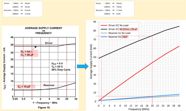
    My customer compared Figure 5-2 and Figure 10 in the previous datasheet.
    The receiver-side current looks smaller, but the driver current looks larger.
    At 1MHz, the receiver current reduced by ~3mA but the driver current increased by ~16mA.
    So the total current increased by ~13mA.
    It looks like power dissipation is increased. Is this correct?

    Also, could you elaborate on why you mentioned that the Figure5-2 includes ICC + IOUT + I_AC_Loss (some power current is lost due to output frequency)?
    I think ICC includes IOUT + I_AC_Loss.

    Best regards,
    Kazuki Itoh

  • The driver current includes the current that flows over the bus and through the termination resistors. The new driver generates a voltage drop of about 2.65 V over the termination (which is more than the old driver, so the current is higher); to compute the power dissipation in the chip itself, you have to subtract that.

    Figure 5-2 shows the current that flows into VCC and out of GND. This includes the current that the driver consumes itself (both when idle, and the frequency-dependent current to (dis)charge the MOSFET gates), and the load current. ICC is usually defined to be the total current, but in this case, it's the idle current with not load.

  • Hi Itoh-san,


    Clemens is 100% correct in his analysis - but I will summarize quickly. 

    1. The average VOD is going to be outputting higher than the old device due to the new die - which means more average current during operation to keep that higher typical output voltage. That will lead to more current from VCC - so there could be a larger power consumption. The ICC in the electrical specs is specifically unloaded current  - that is generally where you will see the most improvement in power - i.e. when the bus is unloaded and idle. You need at least to be able to provide ~28mA of current to hit basic RS-485 1.5V spec across 54 ohms and there is very little margin above that on old device. Essentially the difference is due to the drive strength typically being stronger on new material.  

    2. Figure 5-2 I mentioned multiple losses because of how we specify ICC. ICC at a high level is current flowing into the VCC pin - however the ICC that we report in the datasheet is basically measuring ICC(q) or the quiescent supply current of the device when it is unloaded - basically what is the current this device is going to consume regardless of loading - as this current is pure loss it isn't  providing a signal to a load - this is the base current is going to be present in every ICC measurement. 

    However when you load the output ICC is going to increase from what is reported in datasheet because the output is now loaded. At this time if you measure the ICC current during operation the current measured is basically a combination of three things:

    ICC = ICC(idle; no load) + I_OUT (Current driving load - which is termination resistor) + I_LOSS_AC (there is a frequency component - higher frequency signals will cause more AC switching losses through driver - i.e. why the X-axis is based on frequency) 

    ICC(idle; no load) + IOUT will remain pretty constant in the same operation environment regardless of frequency - but AC losses will vary with data-rate.

    I will be as transparent as I can - these are 1 IC tests - we sweep across 1IC they are not statistically significant graphs. I.e. customer will have to do testing themselves in their system because while our guidelines that I have provided above should give a good idea on what changes they may expect they need to confirm in their old systems and they aren't going to an extremely detailed analysis of every finite point- basically what I have given is what I can give you. 

    Best,

    Parker Dodson  

  • Hi Parker-san,

    I understand that the I_OUT increased due to the better driver strength.

    Has ICC(idle; no load) and I_LOSS_AC decreased by the PCN?

    Best regards,

    Kazuki Itoh

  • Itoh-san,

    1) I_LOSS_AC is not something we directly specify - so we don't have a number. Figure 5-2 includes it in its typical graph to give an idea of how frequency relates to ICC. 

    2) yes the typical most likely has decreased as I have already said - we don't give a minimum and system needs to be designed with respect to max possible condition. It feels as you keep fishing for us to give you a number that I am not going to give you. All the information about the PCN has already been given - they need to do their own test and qualification if there is concern. 

    Best,

    Parker Dodson

  • Hi Parker-san,

    Sorry for the repetitive questions.
    My customer is repetitively asking us to provide easy and conclusive comment to reduce the extra evaluation or consideration effort for PCN.
    I understand it's not that easy.
    Also it was a bit hard to me to have the customer interpret the difference between old Figure 10 and new Figure 5-2.
    Thank you so much for your support.

    Best regards,
    Kazuki Itoh

  • Itoh-san,

    I understand this is moreso coming from the customer than you directly - I wasn't trying to be rude so I apologize if it came off that way - I was just trying to be as clear I could (sometimes that can come off a little bit more blunt so I apologize again). 

    Unfortunately they will have to do some qualification of the new material if they want to be able to know what to expect typically from the new device - this is more or less expected on all of our material that is being updated at least with respect to RS-485 and RS-232 (those are what I cover so I don't want to speak for other types of parts going through this change) . We don't really have a concern that there is compatibility issues between devices - but typical room temperature measurements will be different and if there is concern there or they want to set up ICT boundary points based on those room temperature measurements for new material they will have to do some qualification. 

    Best,

    Parker Dodson