This thread has been locked.

If you have a related question, please click the "Ask a related question" button in the top right corner. The newly created question will be automatically linked to this question.

DP83867E: interference during power cycle causes system crash of the PHY

Part Number: DP83867E

Hello Team 

can you please help with the following issue:

"Our device with the integrated DP83867 module is connected to a second end device (only supporting 100Mbit/s).
During the power cycle, the DP83867 module is supposedly disturbed and hangs up. This can be recognized
This can be recognized by the fact that the link LED of the DP83867 no longer goes out when the cable is disconnected --> here the PHY no longer seems to change the link.
to change the link. Everything continues to work on the remote station without any problems (link up and down works). In addition
the internal registers of the DP83867 can still be accessed. However, they only provide implausible static values. A SW reset
via the registers has already been attempted and is not processed by the PHY."

Question already answered from TI SEM Team: 

- Is the remote station also a DP83867?
--> No, but the exact manufacturer is not known


- Does the problem always occur, or what exactly does "Power Cycles the DP83867 module is supposedly disturbed / confused" mean?
--> The problem occurs sporadically during the power cycle of the remote station. Not during the power cycle of the DP83867


- What exactly happens during the power cycle in the event of an error? Is the power-up sequence adhered to? It may be possible to measure the power-up sequence with a scope.

--> Only the remote station is restarted or switched on again. Until then, everything seems to be OK with the DP83867, so I would rule out the power-up sequence for the time being.Before the power cycle problem, communication via MDIO/MDC is possible without any problems. Communication is only disrupted when the error occurs.
At this point, the PHY appears to respond to the request with data via MDIO/MDC. However, always with the same date, regardless of the address addressed.


- What does it mean that the DP83867 can still be reached, but the data is inconsistent?
--> The MDIO interface is working. However, the DP83867 always responds with the same date. Regardless of the address addressed. (However, this still needs to be verified by measurement on the target).


- SW Restart is to write the value 0x4000 to register 0x1F. Has this been tried?
Neither a SW restart via register 0x1F nor a reset to register 0x0 brings the PHY back to normal operation. Only a hardware reset via GPIO provides a remedy.

- Is it possible to reset the PHY via GPIO and does it work again afterwards?
--> This seems to work.

What Ethernet cable length is used in the test?  Short cable, e.g. <1m? Perhaps try a different cable length, e.g. 20m, and see if the error pattern changes.

--Different cable lengths have no influence on the behavior.

Thanks 

Jan

  • Hi Jan,

    Correct me if my understanding is wrong. Is the PHY not able to recognize the link down scenario after power cycle in DP83867PHY based on the Link LED indication?

    Could you provide a register dump between the abnormal case for both cable is connected and cable is disconnected.

    --

    Regards,

    Hillman Lin

  • Hello Lin, 

    the customer sent the register dump below:

    As described above, the register contents during the fault condition are not reliable, as the PHY is hanging. However, here is the last register content:
    With Cable plugged in at the failure case:
    addr=01 reg=00 data=A231
    addr=01 reg=01 data=A231
    addr=01 reg=02 data=A231
    addr=01 reg=03 data=A231
    addr=01 reg=04 data=A231
    addr=01 reg=05 data=A231
    addr=01 reg=06 data=A231
    addr=01 reg=07 data=A231
    addr=01 reg=08 data=A231
    addr=01 reg=09 data=A231
    addr=01 reg=0a data=A231
    addr=01 reg=0b data=A231
    addr=01 reg=0c data=A231
    addr=01 reg=0d data=401F
    addr=01 reg=0e data=A231
    addr=01 reg=0f data=A231
    addr=01 reg=10 data=A231
    addr=01 reg=11 data=A231
    addr=01 reg=12 data=A231
    addr=01 reg=13 data=A231
    addr=01 reg=14 data=A231
    addr=01 reg=15 data=A231
    addr=01 reg=16 data=A231
    addr=01 reg=17 data=A231
    addr=01 reg=18 data=A231
    addr=01 reg=19 data=A231
    addr=01 reg=1a data=A231
    addr=01 reg=1b data=A231
    addr=01 reg=1c data=A231
    addr=01 reg=1d data=A231
    addr=01 reg=1e data=A231
    addr=01 reg=1f data=A231
    With Cable unplugged:
    addr=01 reg=00 data=A231
    addr=01 reg=01 data=A231
    addr=01 reg=02 data=A231
    addr=01 reg=03 data=A231
    addr=01 reg=04 data=A231
    addr=01 reg=05 data=A231
    addr=01 reg=06 data=A231
    addr=01 reg=07 data=A231
    addr=01 reg=08 data=A231
    addr=01 reg=09 data=A231
    addr=01 reg=0a data=A231
    addr=01 reg=0b data=A231
    addr=01 reg=0c data=A231
    addr=01 reg=0d data=401F
    addr=01 reg=0e data=A231
    addr=01 reg=0f data=A231
    addr=01 reg=10 data=A231
    addr=01 reg=11 data=A231
    addr=01 reg=12 data=A231
    addr=01 reg=13 data=A231
    addr=01 reg=14 data=A231
    addr=01 reg=15 data=A231
    addr=01 reg=16 data=A231
    addr=01 reg=17 data=A231
    addr=01 reg=18 data=A231
    addr=01 reg=19 data=A231
    addr=01 reg=1a data=A231
    addr=01 reg=1b data=A231
    addr=01 reg=1c data=A231
    addr=01 reg=1d data=A231
    addr=01 reg=1e data=A231
    addr=01 reg=1f data=A231
    Without failure and cable plugged:
    addr=01 reg=00 data=1140
    addr=01 reg=01 data=796D
    addr=01 reg=02 data=2000
    addr=01 reg=03 data=A231
    addr=01 reg=04 data=01E1
    addr=01 reg=05 data=C5E1
    addr=01 reg=06 data=006D
    addr=01 reg=07 data=2001
    addr=01 reg=08 data=6801
    addr=01 reg=09 data=0300
    addr=01 reg=0a data=0000
    addr=01 reg=0b data=0000
    addr=01 reg=0c data=0000
    addr=01 reg=0d data=401F
    addr=01 reg=0e data=0088
    addr=01 reg=0f data=3000
    addr=01 reg=10 data=5048
    addr=01 reg=11 data=6F02
    addr=01 reg=12 data=0000
    addr=01 reg=13 data=0000
    addr=01 reg=14 data=29C7
    addr=01 reg=15 data=0000
    addr=01 reg=16 data=0000
    addr=01 reg=17 data=0040
    addr=01 reg=18 data=6B56
    addr=01 reg=19 data=4444
    addr=01 reg=1a data=0002
    addr=01 reg=1b data=0000
    addr=01 reg=1c data=0000
    addr=01 reg=1d data=0000
    addr=01 reg=1e data=0002
    addr=01 reg=1f data=0000
    Without failure and cable unplugged:
    addr=01 reg=00 data=1140
    addr=01 reg=01 data=7949
    addr=01 reg=02 data=2000
    addr=01 reg=03 data=A231
    addr=01 reg=04 data=01E1
    addr=01 reg=05 data=0000
    addr=01 reg=06 data=0064
    addr=01 reg=07 data=2001
    addr=01 reg=08 data=0000
    addr=01 reg=09 data=0300
    addr=01 reg=0a data=0000
    addr=01 reg=0b data=0000
    addr=01 reg=0c data=0000
    addr=01 reg=0d data=401F
    addr=01 reg=0e data=0088
    addr=01 reg=0f data=3000
    addr=01 reg=10 data=5048
    addr=01 reg=11 data=0002
    addr=01 reg=12 data=0000
    addr=01 reg=13 data=0440
    addr=01 reg=14 data=29C7
    addr=01 reg=15 data=0000
    addr=01 reg=16 data=0000
    addr=01 reg=17 data=0040
    addr=01 reg=18 data=6B56
    addr=01 reg=19 data=4444
    addr=01 reg=1a data=0002
    addr=01 reg=1b data=0000
    addr=01 reg=1c data=0000
    addr=01 reg=1d data=0000
    addr=01 reg=1e data=0002
    addr=01 reg=1f data=0000

  • Hi Jan,

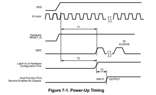
    Based on the register dump, it seems like the PHY is not operating in the correct state during power cycle. It seems like an power up sequence issue. 

    My hypothesis is the PHY power up timing might operate in the margin which result in DP83867PHY in abnormal state sometime during power up.

    If possible, could you probe the VDDA, VDDIO, MDC, and XI clock pin in the scope during power up and see if they fit within the specification in the datasheet?

    --

    Regards,

    Hillman Lin