My customer is having an issue where an RS485 bus appears fully functional for several hundred hours, but begins to miss pings and quickly loses communication entirely. The receiving device has a 24V pump that seems to increase communication issues - presumably through EMI. The pump has a snubber, but may still be causing slow degradation of the transceiver. Any ideas on how the transceivers may be getting degraded would be greatly appreciated. They are currently used with 100 Ohm impedance matching resistors - series resistors have been replaced with jumpers.
Thank you
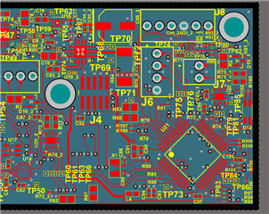
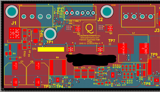
pump driver: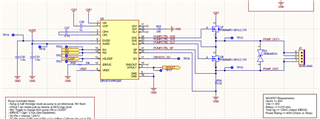
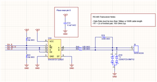
Transceiver: