This thread has been locked.

If you have a related question, please click the "Ask a related question" button in the top right corner. The newly created question will be automatically linked to this question.

THVD1520: equivalent circuit for long twisted pair cable for RS485 communication

Part Number: THVD1520

Hi Team,

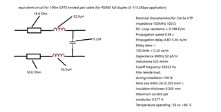
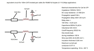
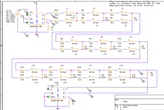
 we are using THVD1520 for RS485 communication, the configuration is two twisted pair cable for full duplex RS485, distance is 1000 meters and baudrate is 115.2Kbps. we need make equivalent circuit to simulate the 1000 meter twisted pair cable, do you have such circuit? which wire size is appropriate for our application (18/22/24 AWG?), please advise, thanks a lot.

Best

Gu

  • Hi Gu,

    I typically see CAT5 cable being used for RS485 communication. The characteristic capacitance of a cat5 cable is about 50pF/m. For inductance I would estimate about 500nH/m.

    Trying to build an equivalent circuit to mimic the actual load of a 1000 meter cable is kind of tricky. Just using one capacitance and 1 inductor as the load for example wouldn't be very accurate. In theory the cable is made up of infinitely small inductors in series and capacitances in parallel with other infinitely small inductors in series and caps in parallel. It would be more accurate if you tried to create this with as many inductors and capacitors as you can. For example with a 1000m cable the total cap would be 50nF and the total inductance would be 500uH. If you stack a 100uH inductor in series with 4 other 100uH inductors and have 10nF capacitors in-between each inductor the total load would still be 500uH and 50nF but you would likely get a more accurate cable load than you would using just 1 inductor and 1 capacitor to simulate the load.

     -Bobby

  • Hi Bob,

     thank you so much for your advice. I am thinking use below circuit to simulate 100 meter CAT5 twisted pair cable, so for 1000 meters, I just need connect 10 of this circuit in series, does it make sense? please advise. thanks.

    Best

    Gu

  • Hi Cheng,

    I will need to double check with a colleague of mine. The measurements provided for characteristic parameters of a CAT5 cable are based off a single wire. Since your communication is using differential, we may need to modify how the actual load is into an equivalent load. (I don't think the capacitive load is between the two wires, I assume it's in reference to GND but need to double check).

    -Bobby

  • Hi Bob,

     thanks for your quick reply, I modified the circuit as you suggested for the cap. below is the new diagram, as for the value of the characteristic parameters, please help me to define. I know little of this simulation/calculation. our target is RS485 full duplex 3000 feet @ 115.2kbps, the number of devices on the RS485 bus is variable, but shall not exceed the limits of the RS485 bus standard. if you can provide me the calculations, it will be very helpful, so I can do it myself if change to different gauge wire.  

     Best
    Gu

  • Hi Cheng,

    I spoke with my colleague who stated that the more accurate model should be the first one you pointed out Here:

    This is since the twisted pair are connected to the RS485 lines and not twisted together with a signal wire together with a GND wire. 

    He also suggested reaching out to the cable manufacturer you plan to use to see if they may have a datasheet with values and may be able to use a VNA to get real RLC values for you which is frequency dependent so they should be able to test using your baudrate. This would probably provide better values than using the assumed wire characteristics that we make with a general CAT5 cable. 

    I know little of this simulation/calculation. our target is RS485 full duplex 3000 feet @ 115.2kbps, the number of devices on the RS485 bus is variable, but shall not exceed the limits of the RS485 bus standard. if you can provide me the calculations

    I don't think we have any special calculations here. For the standard they use something called a unit load. This basically just calls out how much leakage current each receiver can have. 1 unit load I believe is 1mA and the most allowed is 32 unit loads. Most modern RS485 receivers are rated to much lower unit loads and are measured in fractions of 1 unit load. THVD1520 for example has a unit load of 1/32. So you could in theory load up an entire bus up to 256 THVD1520s to hit the standard limit. If you wanted to simulate this, I think you can just add some resistors to the bus load to leak current onto the bus. 

    -Bobby

  • Hi Bob,

     Thanks for your help. I will make pspice simulation and test circuit to evaluate. if we don't want to use long distance cable for every development test setup, is there any off the shelf twisted pair equivalent board to use? or is there other method to simulate long distance twisted cable in the real development test hardware. 

    Best

    Gu

  • Hi Gu,

    The most important aspect of the cable will be the characteristic impedance. Be sure that the cable you use for testing has the same impedance as that which will be used in the end application. Ideally, these should be the same brand and part number as you may see some variance in quality between cable options. Apart from this, the cable length and termination placement that will be used in the end application should match . 

    Using a physically long cable is the most accurate way to estimate a transceiver's performance in an end application. This is because it takes into account not only the parasitic properties of the cable, but also the impedance characteristics, reflection behavior, and propagation timings that are expected in the real system. Smaller solutions such as load simulators will mainly only address the impedance and parasitic characteristics without being able to properly simulate these other behaviors. 

    Regards,
    Eric Schott

  • Hi Eric,

     thanks for your advice. we will make some test and debug setup, we want to use real long cable in the test setups and use load simulator board for firmware code development. I made a Pspice simulation model like below for CAT5 24 AWG 1000 meters simulation, would you please take a look and advise whether I need add/change anything for the cable simulation circuit? thanks.

    Best

    Gu

  • Hi Gu,

    There should be two 120 ohm termination resistors on the bus. One at the beginning of the transmission line and one at the end of transmission line. I only see one 120 ohm resistor in your set up. 

    -Bobby

  • Hi Bob,

     thanks a lot for your help, I added the termination resistor on both end.

    Best

    Gu