This thread has been locked.

If you have a related question, please click the "Ask a related question" button in the top right corner. The newly created question will be automatically linked to this question.

TPD12S016: I2c always Nacks

Part Number: TPD12S016

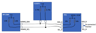
I'm currently using the TPD12S016 in a carrier board with a Raspberry Pi compute 4 module.

With the new Bookworm Linux versio, The Pi wants to know the monitor details. 

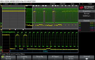
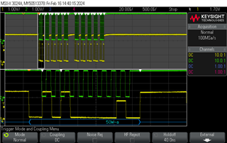
After pulg in the screen the pi sends a message over I2C to the screen. If I look at the signals on the HDMI port itself the write to address 50 is acknowledged SDA_B. If I check at the SDA_A side it gets nacked. 

The level of the nack puls is about 2,7V. If I load the SDA_A with a 3K9 resistor to GND the Nack is interpreted as an ACK by the pi and the second byte is send. data comming from the screen is not recognised due to the load on the bus.

I have added 2 pictures, Usb_1 measured on SCL_A SDA_A and Usb_2 measured on SCL_B & SDA_B.
What can I do to get things working OK?


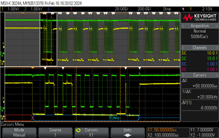
The picture below is from the Raspberry pi IO board, with the same compute module and the same monitor

  • Hello Marc, if I am understanding the data correctly, it appears that the A side interface is not able to drive the SDA_A signal low. Would it be possible to share a connection diagram or perhaps schematic? Are there any additional pull ups on the A side that are influencing the signal?

    Regards, Zack

  • Hi Zack,

    The raspberry pi compute 4 uses a CL02F3 esd protection. resistors R1 and R2 in the CL02F3 are connected to HDMI0_SDA and HDMI0_SCL, the other end of thye resistors are connected to +5V. The resistors are 1K75 each. 
    It's a rather strong pull-up. 

  • Hi Marc,

    Zack is OoO today, could you please share the TPD12S016 schematic to us? Thank you.

    Best Regards,

    Kuno

  • Hi Marc, I made some assumptions here... can you confirm that this is the setup/configuration?

    If so I believe the issue is the ESD device that is pulling up to 5V. I may be misunderstanding the RPi CM4 HW, but it seems that it is built to directly connect to an HDMI connector/monitor. I think the pullup presented by the ESD device is making it hard for the TPD device to drive a logic low signal onto the SDA line (note the 10K pullup/3.3V supply on the A side for the TPD device.) Normally this added ESD protection would sit on the connector side of the circuit - not between the processor and TPD device. Note the TPD has built in ESD protection up to 8KV - if the higher level of ESD protection is needed at the connector, the ESD device should be moved to the B side of the TPD.

    Also, do you know what the pullup voltage is internal to the RPi for these HDMI I2C lines? Is it possible to disable the internal pull ups and reply on the pullups of the TPD device?

    Regarding the TPD device, can you confirm the level for VCCA? (datasheet max is 3.6V)

    Regards, Zack

  • Hi Zack, I have skipped the I³C buffers inside the TPD12S016 and connect the I2C from the HDMI connector directly to the I³C of the Compute 4 module.
    The I³C is now read correctly. The control lines are ESD protected on the compute module, the Differential lines aren't, 
    I will keep the TPD12S016 to protect thes differential lines and rely on the esd protection for the I2C on the Compute module.  I will reroute the I²C tracks directly onto the compute module.
    Thanks for your support.

  • Awesome. Glad to know all is working now Marc, thank you for the followup.