This thread has been locked.

If you have a related question, please click the "Ask a related question" button in the top right corner. The newly created question will be automatically linked to this question.

ISO1050 CAN Termination

Other Parts Discussed in Thread: ISO1050

Hi,


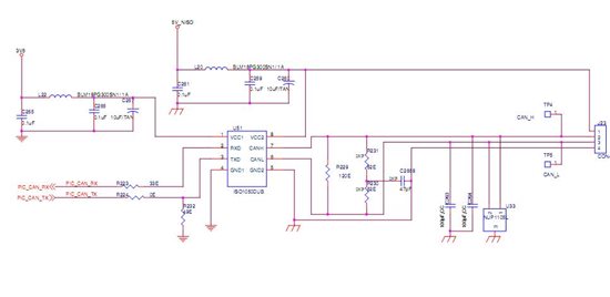
I am little confused with the CAN termination used in ISO1050 datasheet.

It is 60 ohm.(Non split) and 330 ohm split

Usually we use 120 ohm or split termination of 60 ohm.

Why is it mentioned to be 60 ohm?

My node is receive only and it is not the last node do I have to terminate the CAN Bus?


Regards,

Chaitanya


  • Dear Chaitanya,

    your usual termination of 120 ohms (or the split termination of 60 ohms) at both ends of the bus is correct. What the data sheet presents are test circuits in which the terminations of both bus ends are lumped together to establish the maximum load requirement of a CAN transceiver. Representing the two parallel 120 ohm terminations through one lumped load yields a single differential load of 60 ohms (or the lumped, split termination of 30 ohms).

    In addition the two 330 ohms you see in some test circuits represent the maximum common-mode loading, or loading of the signal conductors, CANH and CANL, against ground. The sum of  this common-mode load and the differential load thorugh termination represents the total load for a CAN transceiver.

    Best regards,

    Thomas.

  • Hi Thomas,


    Thanks for such a quick reply.

    I have taken the reference of the ISO1050 eval board schematic.

    I attaching my schematic.

    I suppose now I should not have the 60 ohm termination in my schematic and usual 120 ohm differential is sufficint or 60 ohms split.

    Pls let me know if any mistakes you have found in that.7723.ISO CAN.pdf

    Another question,

    Do you think we should have the termination in each CAN transreceiver ,this is unlike the RS485 where only one termination at the end and not like RS422 where every one is 100 ohm terminated?


    Regards,


    Chaitanya


  • Chaitanya,

    1) RS-422 is similar but not equally terminated to RS-485. The difference is that RS-485 is a multi-point bus, which means every node can transmit and receive. However, only one driver can be active at a time. So if one node starts transmitting (or driving the bus) all other nodes must be in receive mode. Ther termination is a 120 ohms at both bus ends.

    RS-422 is a multi-drop bus, which means that at all times there is only one dedicated driver (typically located at one end of the bus, while the other nodes are always receivers. Ther termination is a 100 ohm resistor at the one bus end opposite of the driver.

    CAN is similar to RS-485 in the way that every node can tramist and receive. Therefore 120 ohms termination is required at both bus ends. Some designers have termination on each node. This termination however must be made selectable via jumpers. And in your user manual to the customer, there must be an instruction included saying ONLY THE LAST TRANSCEIVER AT EACH BUS END CAN HAVE THE TERMINATION SELECTED WHILE ALL OTHER CARD HAVE TO HAVE THE JUMPERS REMOVED TO DISABLE THEIR TERMINATION.

    2) In your schematics you have two terminations in parallel, the 120 ohms resistor and the split termination. WHY?

    I suggest to remove the 120 ohms resistor and to add two jumpers between the 62 ohms resistors and the data lines (CANH and CANL) so you can select for the termination to be active or not.

    3) I am expecting a training slide set from our CAN specialist Scott Monroe which I will send you later today.

    regards,

    Thomas

  • Chaitanya,

    please find attached the CAN training with some termination examples from our CAN Grand Master Scott Monroe. You can also contact him directly at s-monroe1@ti.com.

    best regards,

    Thomas

    2011-09-06 Texas Instruments CAN PHY Technical Training.pdf
  • Hello Thomas,


    1)It is an excellent post for RS422,RS485 and CAN teminations.

    The document I have downloaded and I will study it.

    "In your schematics you have two terminations in parallel, the 120 ohms resistor and the split termination. WHY?"

    Actually I have put a provision for both the terminations and I have made split as DNP (Do not populate) Sorry I did not mentioned this earlier.

    And yes I will add the Jumper and User Manual update.Really thankful to you for this ....

    Last question:

    Does it matter if I use Spilt on my Unit( say it is the last one)  but the main ECU which is probably the first is using Non-split termination,will it work then?

    Is it important to know what terminations the first node is using,spilt or non-split?


    Regards,

    Chaitanya


  • Hello Chaitanya,

    the document you received was created by Scott Monroe. I only contributed to the last slide which covers the grounding techniquies for an isolated interface. So all credit goes to Scott. 

    With regards to the split termination question I am not 100% certain.

    While differentially there should be no difference between the split and non-split termination, there could be some timing difference when returning from the domionant state to the recessive state between the split termination and the non-split termination. For this question I really would have to consult Scott who actually has worked with various termination schemes.

    I will forward this mail to Scott who is currently travelling and might not have access to the forum.

    Regards, Thomas


  • HI:

    we are using ISO1050 now in our project,but i got  a problem for GROUND, according to the document you uploaded, can you please tell me how to connect Cspllit ground, if this ground is connected to the protection ground or be connected to the ISO ground? and why?


    thank you !

  • Hi Tian,

    The CSPLIT capacitor will be connected to the GND2 ground. This is because GND2 is with respect to the CAN transceiver die, and CSPLIT capacitor will be creating a low pass filter for common mode noise on the bus. Therefore you want the two to be referenced to the same point.

    Thanks,

    John

  • Hi Hohn:

    Thank you so much~

    Tian

  • can you send me that document too please?

    guenes (at) ieee (dot) org

  • Hi Guenes,

    If you scroll up in this thread the PDF document is attached in a response from Thomas. In addition I have a short wiki on CAN termination which can be found below.

    http://e2e.ti.com/support/interface/industrial_interface/w/industrial_interface/2513.can-termination-techniques.aspx

    Thanks,

    John