This thread has been locked.

If you have a related question, please click the "Ask a related question" button in the top right corner. The newly created question will be automatically linked to this question.

SN65HVD22: Cable length, signaling rate and nodes

Part Number: SN65HVD22
Other Parts Discussed in Thread: THVD2450

Hi Team,

Cable length and signaling rate of this product is up to1200m at 500 kbps (with slew rate limit) and node is Up to 256.

Dose it mean it can use with 1200m, 500kbps and 256 nodes?

Or it need to reduce cable length or signaling rate in the case of 256 nodes?

If need to reduce, please tell me the spec.

Best Regards,

  • Hi Takahashi-san,

    This device can operate with a bus length of 1.2km, 500kbps, and up to 256 nodes, but that statement in the datasheet makes some major assumptions. 

    1. It assumes that the bus is properly terminated and setup (it needs to be terminated properly and the network topology cannot introduce noise issues - so if possible daisy chaining is the ideal network topology) 

    2. It assumes you are using Belden 3105A cable for the transmission medium. So this rating prediction is based on this specific cable - other cables were not included in the analysis (not saying other cables can't work - but the statement in the datasheet is based on the Belden 3105A cable)

    3. It assumes an allowable eye pattern jitter of 15% - so it assumes a relatively larger jitter. 

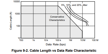
    Largely this "statement" isn't special to the SN65HVD22 - its just a benefit on using slower devices.  The below chart is generalized to RS-485 busses and the "slew rate limited" devices can just be thought as "slower" devices - so you can still use this chart as a reference. 

    It basically comes from this chart (the jitter lines if continued to 500kbps would put the 1.2km point between 10% and 20% jitter lines).

    The conservative "value" here is still around 125kbps at 1.2km with almost near 0%  jitter added by bus - but you can push it higher with jitter also increasing. 

    Please let me know if you have any other questions and I will see what I can do!

    Best,

    Parker Dodson

  • Hi Parker-san,

    Thank you for the detailed explanation.

    Where is source of the chart?

    I checked data sheet and several application notes but I couldn't find it.

  • Hi Takahashi-san,

    So this figure is standard to RS-485 and RS-422 devices (you will see this graph across industry when looking into speed v. distance of RS-485 or RS-422 devices - basically my point is that this is not just TI this is a standard understanding of the speed v. distance).

    The original graph comes directly from the RS-422 standard - specifically "TIA/EIA-422-B Annex-A guideline" - where RS-485 and RS-422 have the same distance vs.  speed characteristics (there are differences between RS-422 and RS-485 - but speed v. distance is the same). 

    However with that being said we do tend to put this graph  in a lot of our newer device datasheets - especially if they are faster devices - for example if you look at the THVD2450 the following graph is included:

    Which is the same as the one I originally attached in my first reply. 

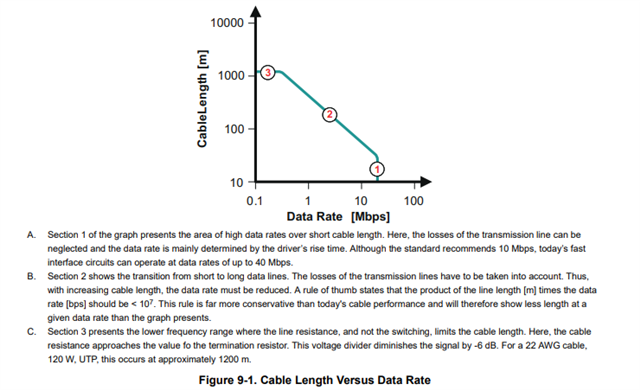
    This figure is also more or less shown in our RS-485 design guide (without the jitter lines)

    *Please note that the RS-485 design guide is a bit out of date as our devices now can go up to 50Mbps instead of 40Mbps as mentioned in note "A" on the graph.

    We also do have a graph that has the distance in meters as well as feet so you can see in both units of length:

    RS485 speed vs distance - Interface forum - Interface - TI ...

    Please let me know if you have any other questions!

    Best,

    Parker Dodson 

  • Hi Parker-san,

    Thank you for your answer.

    I understand very well.