Part Number: DS90UB960-Q1
Dear Team,
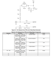
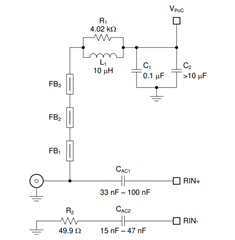
Below is the PoC circuit.
My questions are given below.
- Why 3 ferrite beads (FB1,FB2,FB3) are connected in series.
- How to design these ferrite beads
- Why there is a resistor connected in parallel with inductor(R1 & L1)
Regards
HARI