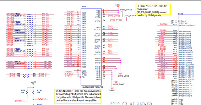
Part Number: SN75LVDS82
Other Parts Discussed in Thread: SN75LVDS83
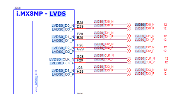
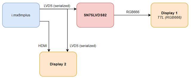
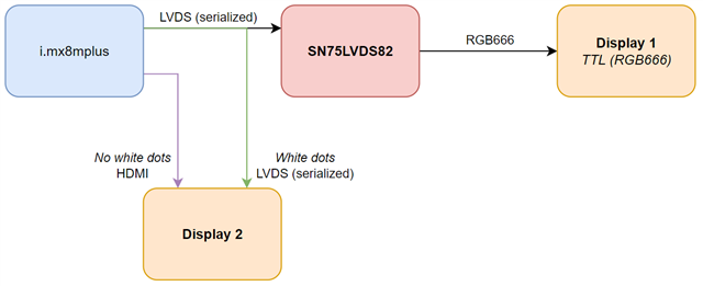
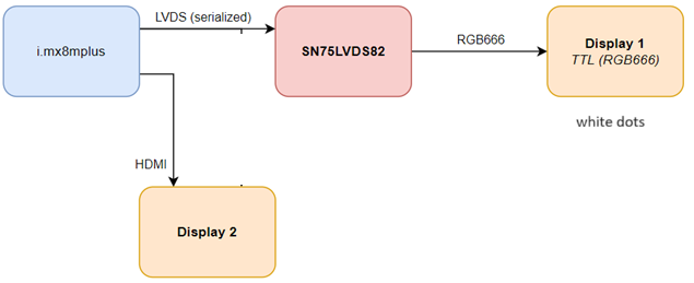
Can SN75LVDS82 works with i.mx8mplus's LVDS output?
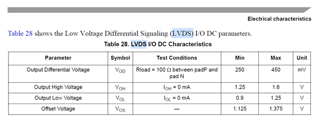
I was told the i.mx8mplus's LVDS1.8 output is 1.8V but SN75LVDS82's operation voltage is 3.3VDS.
Part Number: SN75LVDS82
Other Parts Discussed in Thread: SN75LVDS83
Can SN75LVDS82 works with i.mx8mplus's LVDS output?
I was told the i.mx8mplus's LVDS1.8 output is 1.8V but SN75LVDS82's operation voltage is 3.3VDS.