
This thread has been locked.
If you have a related question, please click the "Ask a related question" button in the top right corner. The newly created question will be automatically linked to this question.


Hi Roy,
Thank you for reaching out with your questions.
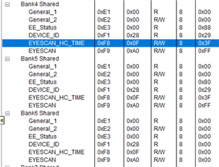
Could you please provide me the following to assist in debug of your issue:
Best,
David
:200000002200000410038100101381001023810010338100FFFFFFFFFFFFFFFFFFFFFFFF16
:20002000FFFFFFFFFFFFFFFFFFFFFFFFFFFFFFFFFFFFFFFFFFFFFFFFFFFFFFFFFFFFFFFFE0
:20004000FFFFFFFFFFFFFFFFFFFFFFFFFFFFFFFFFFFFFFFFFFFFFFFFFFFFFFFFFFFFFFFFC0
:20006000FFFFFFFFFFFFFFFFFFFFFFFFFFFFFFFFFFFFFFFFFFFFFFFFFFFFFFFFFFFFFFFFA0
:20008000FFFFFFFFFFFFFFFFFFFFFFFFFFFFFFFFFFFFFFFFFFFFFFFFFFFFFFFFFFFFFFFF80
:2000A000FFFFFFFFFFFFFFFFFFFFFFFFFFFFFFFFFFFFFFFFFFFFFFFFFFFFFFFFFFFFFFFF60
:2000C000FFFFFFFFFFFFFFFFFFFFFFFFFFFFFFFFFFFFFFFFFFFFFFFFFFFFFFFFFFFFFFFF40
:2000E000FFFFFFFFFFFFFFFFFFFFFFFFFFFFFFFFFFFFFFFFFFFFFFFFFFFFFFFFFFFF00001E
:00000001FF
:200000002200000410038100101381001023810010338100FFFFFFFFFFFFFFFFFFFFFFFF16
:20002000FFFFFFFFFFFFFFFFFFFFFFFFFFFFFFFFFFFFFFFFFFFFFFFFFFFFFFFFFFFFFFFFE0
:20004000FFFFFFFFFFFFFFFFFFFFFFFFFFFFFFFFFFFFFFFFFFFFFFFFFFFFFFFFFFFFFFFFC0
:20006000FFFFFFFFFFFFFFFFFFFFFFFFFFFFFFFFFFFFFFFFFFFFFFFFFFFFFFFFFFFFFFFFA0
:20008000FFFFFFFFFFFFFFFFFFFFFFFFFFFFFFFFFFFFFFFFFFFFFFFFFFFFFFFFFFFFFFFF80
:2000A000FFFFFFFFFFFFFFFFFFFFFFFFFFFFFFFFFFFFFFFFFFFFFFFFFFFFFFFFFFFFFFFF60
:2000C000FFFFFFFFFFFFFFFFFFFFFFFFFFFFFFFFFFFFFFFFFFFFFFFFFFFFFFFFFFFFFFFF40
:2000E000FFFFFFFFFFFFFFFFFFFFFFFFFFFFFFFFFFFFFFFFFFFFFFFFFFFFFFFFFFFF00001E
:00000001FF
Hi, David,
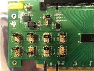
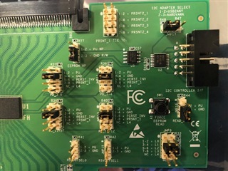
For the eeprom load incomplete error, we fixed it by changing the JMP7 to 3-4, and change the address map to 0x26 and 0x27 in the configuration. Maybe R25 in the Eval board has a wrong value.
Now we need to figure out the receiver detect issue.
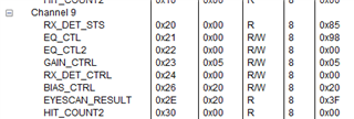
1. The receiver detect in the lowLevel Page shows channel 9 with RX_DET_STS = 0x85
2. My switch on the motherboard(a PEX89104) sees a 0xffb9 in its receiver detect register, or lane 2, 3, 6 don't see receiver detect.
Appreciate your help,
Huiji
Hi Roy, Huiji,
Thank you for the update on the addressing issue.
Given the current symptoms, I am thinking this may be an RX Detect synchronization issue between the redriver and the switch. Could you please place the shunts on JMP10, JMP11, JMP12, and JMP13 to position 5-6 instead of position 3-4? This will tie the Power Down (PD) pins to PERST_INV.
When is this symptom noticeable? Is it only on system power up, or every time PERST# is asserted? Or a different scenario?
Best,
David
Hi, David,
After we changed the JMP10-13 setting, the receiver detect from host still same. Now the receiver detect register reading is 0xd7ff. And the channel 9 RX_Det_sts is still 0x85.
Thanks,
Huiji
Hi Huiji,
Thanks for the update. When you state the switch's RX detect register has a new updated value of 0xD7FF, do you know how this differs from the previous 0xFFB9 value of this register from the previous test? I do not know what these register values imply.
Best,
David
Since our original motherboard does not de-assert and assert PERST, I moved it to a normal motherboard which assert and de-assert PERST. The new receiver detect of 0xd7ff indicates lane 13 and lane 11 are not detected. I will move the setup back to the original motherboard and update you in a bit.
Thanks,
Huiji
Hi Huiji,
Got it - I see the pattern of this register now. Please let me know once you have an updated test result on the original motherboard.
One additional item that I would like to see the result of - if you write 0x40 into channel register 0x04 for each channel that does not show proper RX Detect Status, what is the result of the switch's RX detection register?
Best,
David
After I moved the JMP10-13 from 3-4 to 5-6 and back to the original setup, the receiver detect register read is back to 0xffb9. And the redriver is showing:
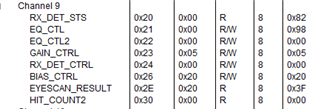
I wrote all the 0x40 with 0x4 on all channels, since I am note sure how the lanes are mapped to channels. But the receiver detect on my motherboard still stays as 0xffb9. After I power cycled the other end (the transmitter), the receiver detect changed to 0xfff9. Meaning 1 lane receiver detect got recovered.
Hi, David,
Correction: I wrote 0x4 to all the RX_DET_CTRL registers. I was not able to write 0x40. The GUI does not allow to write 0x40. I hope what I did is what you wanted.
Thanks,
Huiji
Hi Huiji,
Apologies for the typo - I had meant to state to write 0x4 into register 0x4 for those channels, not 0x40. I'm glad you were able to try this, as this was the intended test.
It is odd to me that the channels that read back an incorrect RX Detect status change on each link-up. When testing the two switches inline without the EVM, is there any RX Detect or link-up issue?
Additionally, i see that the EQ Index is set to Index 2 for Channel 9 - does this phenomenon occur regardless of the EQ Index selected? Typically, the recommendation is to start with the "Default" EQ Index (see below from the programming guide for reference):
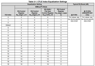
The register names in the GUI are as follows:
Best,
David
Hi, David,
1. When bypass the EVM, the receiver detect is ok @0xffff, meaning all lanes got receiver detect
2. After I restored the eeprom to set the EQ_Index to default, the receiver detect is still @0xffb9.
Thanks,
Huiji
Hi Huiji,
Got it - thank you.
I would have expected a reset of the RX Detect state machine in the DS320PR1601's channel register 0x4 to restart RX detect on the redriver. One other option that you can test is, with PD pins tied to the original position (3-4):
If you have an oscilloscope, could you please also measure the output of redriver channel 9's TX when powering on the device? This can be done with a PCIe Compliance Load Board (CLB - if you have this available). This corresponds to Lane 9 on the x16 CLB.
Best,
David
Hi, David,
I tried your steps on a Gen4 motherboard (not Broadcom switch based), and the lanes trained at Gen4 X8 to start with and Gen4 X16 after the 4 steps. For this motherboard, I don't have access to the receiver detect register.
Then I tried it on my Gen5 motherboard (with Broadcom switch), after power on, the receiver detect on the switch is 0xffb9, and after step4, the register changed to 0xfff9.
We will try to capture the TX lane on scope later.
Thanks,
Huiji
Hi Huiji,
Thanks for the update. Please let me know the capture of the TX output.
I would expect there to be repeated pulses for RX Detect on the TX output (about every 150μs).
Best,
David
Hi, David,
On one line of channel 9, I see the pulse for every 160uS:
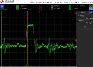
The other line, I don't see any pulse. Once the rx detect is set, does it continue to send the pulse?
Thanks,
Huiji
Hi Huiji,
Thanks for sharing this capture, I expected this pulse.
When you refer to other line, do you mean other channel, or other side of the channel (P vs. N)?
Once RX Detect has detected proper termination on a channel, the device will not pulse this waveform any longer on that channel.
Best,
David
Hi, David,
When I refer the other line, I meant the other side of the channel (P vs. N). This make sense, since the channel 9 returns 0x85. Do you think this is a hardware issue with the setup?
Thanks,
Huiji
Hi Huiji,
Got it, thanks. I would not expect this behavior from one side of the channel.
I am a bit surprised that on the Gen4 platform, there is not an issue seen (after manually forcing RX Detect).
Let me check internally for further guidance on this issue and I will get back to you as soon as possible.
Best,
David
Hi Huiji,
Thank you for your patience.
Have you observed this problem occurring when the MODE pin is set to L2 (SMBus Secondary Mode), or just when MODE = L1 (EEPROM Mode / SMBus Primary Mode)?
Best,
David
Hi, David,
I changed the JMP9 setting from L2 to L1, and the symptom is exactly same.
Thanks,
Huiji
Hi Huiji,
Thanks for confirming with this updated jumper setting.
Please allow me to align with my internal team on this issue.
Best,
David